

RichardS
-
Posts
91 -
Joined
-
Last visited
Content Type
Profiles
Forums
Blogs
Gallery
Downloads
Store
Events
Everything posted by RichardS
-
Quick question about O/D mounting plate on GT6
RichardS replied to RichardS's topic in Gearbox & Overdrive
I tried that but mine only went back about a 1/4 of a notch before the sliding frame hit the cross-member. It now goes back a complete notch into the newly created end notch. 🙂 Richard -
Quick question about O/D mounting plate on GT6
RichardS replied to RichardS's topic in Gearbox & Overdrive
Thanks all for the advice. I've ordered a new plate so I'll have a go at replacing the old one. I've spent most of today re- modelling the driver's seat base so that it goes one complete notch further back to better accommodate my 6ft 3in frame. It now does so but Triumph clearly did not want to make it easy for owners to undertake such an exercise. 🙁 Richard -
Hi Bob I assume that you are talking about top gear? If so, 3000 revs at 40 mph must be wrong although I know nothing about Vitesses specifically. I bought a laser tacho gun for less than £15 on eBay which I use to check tachometers etc. Something like that might be helpful? https://www.ebay.co.uk/itm/DT2234C-Digital-Laser-Rev-Counter-Meter-Non-contact-Tachometer-Rev-Counter-uk/193464331326?_trkparms=aid%3D111001%26algo%3DREC.SEED%26ao%3D1%26asc%3D20160908105057%26meid%3D200495be9ae84930b0c795ce8e1d9134%26pid%3D100675%26rk%3D3%26rkt%3D15%26mehot%3Dnone%26sd%3D181209692912%26itm%3D193464331326%26pmt%3D1%26noa%3D1%26pg%3D2380057%26brand%3DUnbranded&_trksid=p2380057.c100675.m4236&_trkparms=pageci%3Ad4ea48df-b9e3-11ea-a3e5-d6019379fa4d|parentrq%3Aff39ca021720a9bdd3dbc764ffe96628|iid%3A1 Richard
-
I'm sure that this will seem a simple question to the experts on here ... but I want to change the overdrive/chassis mounting plate on my GT6 Mk3 as I can see a small crack in the current plate. For other reasons, I have the transmission tunnel off at the moment so appear to have good access to the two bolts holding the O/D bracket onto the plate and the four bolts holding the mounting plate to the chassis, apart from the one on the drivers side directly below the O/D solenoid which looks a bit of a squeeze. The question is ..... if I release the two bolts holding the O/D bracket onto the plate, will I then be able to jack up the end of the O/D unit with the prop shaft still connected (it has a telescopic joint) sufficiently so as to be able to access the bolt underneath the solenoid and then slide the plate out (forwards or backwards) so as to be able to replace it? Many thanks Richard
-
Thanks for the info and the link. I wonder why the diagram of my exact carb on the Zenith site is not right. I would have thought that they ought to know better than anyone? Anyway, it's all good. 🙂 Richard
-
Thanks Pete I looked at the air filter mounting flange on this diagram: http://zenithcarb.co.uk/carbspec/carburettor/spares/id/4034/ of my 3432 150CDSE carbs which shows the intake vent for the temperature compensator just below the right hand filter mounting bolt. This is the vent which is blanked off by my black gaskets. However, both my carbs, and both the red and black gaskets, have another vent hole just above the each of the bolt holes. For some reason, these two vents are not included on the Zenith diagram. I've now reinstalled the air filter so can I ask if you happen to know what these other two vents are for? Richard
-
That's interesting Adrian .... I haven't removed the carbs from the manifold yet so I may be barking up the wrong tree .... however, when I put an air line into the hole in the front of the carb, (the one which is blocked off by the black gasket), the air rushes out of the aperture in the side of the carb where the "spigot" and valve of the compensator fit into. I wonder if the aperture in your photo is where the air goes into the manifold after the compensator has opened instead of it going through the main choke bore? Richard
-
Today I decided to remove the temp compensators from my GT6 and test/adjust them as described in Adrian's post above as I thought that would be a good introduction to Stromberg tuning before I start on the fiddly stuff. I removed the compensators, cleaned them up a bit and found the everything seemed to be OK from a visual inspection so I then decided to make sure that the air passages through the carbs were clear with an air line, which they were, and then finally turned to the air filter housing to make sure that was all clean and free-flowing. The picture below is what I found. The red gasket looks like the original but the second black gasket clearly has the compensator air passage blocked off so presumably this gasket is from a pre-compensator car? Anyway, I've put the compensators back on and I'll leave them out-of -service for now as I don't want to end up with a lean mixture at higher temperatures as it might already be running a little on the lean side. As a cautionary tale, yesterday we replaced the water temperature gauge which only has L and H with a new gauge and sender which shows the actual temperature. It's a modern gauge and has an LED for night illumination but to simplify the wiring we decided to have the LED on all the time which meant that we just needed one 12V switched feed. We couldn't wire it in parallel with the fuel gauge as we needed 12V for the new gauge so we took the 12V feed from the nearby live side of the rear window demister. When we switched it all on, the gauge read zero and the LED flashed on and off about two or three times a second. After a few minutes with a multimeter, once we had replaced the temperature compensators, we deduced that the rear screen demister was somehow connected through the bimetallic voltage stabiliser .... as, therefore was the windscreen wiper motor and, unbelievably, the ignition system. The ignition system had therefore been receiving a pulsed 10V rather than a steady 12V. 😞 We switched over the two spade connections behind the dash which the last owner had put on the wrong way round and, suddenly, the wipers work properly, the rear screen demister red light shines brightly rather than a dull glow and the engine runs smoothly at idle .... which is exactly what were were hoping to solve with the carb re-tune. It's a voyage of discovery far beyond our wildest dreams. 🙂 Richard

-
Dropping the propshaft out and rear brake cylinder
RichardS replied to RichardS's topic in Drivetrain & Rear Axle
Just to continue this rear brake saga ..... in the absence of any H-clips I decided to rig up a spacer on the end of the brake actuating arm to stop the brake shoe dropping off the edge of the piston. First I did the offside which seemed to be the most problematic but the spacer did the trick. I then went to do the nearside and was puzzled to find that the spacing was different, so I decided to take a few measurements and, guess what, the distance from the backplate to the middle of the piston was about 6 or 7 mm greater on the nearside cylinder than the offside cylinder. The nearside cylinder is clearly the correct part and the brake shoe rides nicely on the centre-line the piston whereas the offside is from something else and allows the shoe to drop off the piston. 😞 As luck would have it, the correct cylinder is the one which was completely seized and I had to abrade the corrosion from the piston to make it work whereas the incorrect cylinder functioned perfectly. Anyway, I've had enough of this so have ordered everything new apart from the drums themselves which are in very good condition. 🙂 Richard -
I've just changed the diff oil seal in my GT6. The level of oil as determined by the level plug is well above the lower edge of the seal so a leaky seal will always let out a lot of oil until the level drops to the same level as the seal. I can't recall another diff which is so extreme in this regard. Richard
-
Dropping the propshaft out and rear brake cylinder
RichardS replied to RichardS's topic in Drivetrain & Rear Axle
Yes, overdrive fitted. Richard -
Dropping the propshaft out and rear brake cylinder
RichardS replied to RichardS's topic in Drivetrain & Rear Axle
Mine has a castellated nut so we torqued it up to the setting in the Haynes manual. 100 - 120 ft lbs if I remember correctly. It certainly felt that tight when we took it off. Richard -
Dropping the propshaft out and rear brake cylinder
RichardS replied to RichardS's topic in Drivetrain & Rear Axle
I'm sure that it's a 3.89:1 as we checked it when we were trying to sort out the speedo problem. One turn of one wheel produces almost 2 turns of the prop shaft We've put in a rubber lip seal now but I knew that something strange was going on when I drilled a small hole in the metal outer face of the old seal and then tried to screw in a self-tapper to force the seal out. I could not screw in the self tapper more than a turn or two before it hit solid metal again. It should have been going into something soft. Rather then drilling deeper we decided to chisel the seal out as I wasn't sure what I would be drilling into. Richard -
Dropping the propshaft out and rear brake cylinder
RichardS replied to RichardS's topic in Drivetrain & Rear Axle
Just to add an interesting postscript to this thread, we attacked the diff oil seal this afternoon and I use the word attacked advisedly. It turned out to be composed of three layers of metal with an outer metal skin and an inner corrugated metal tensioner thing. Between the layers of metal were layers of leather. I therefore wonder if this was the original seal from 1973? If so, I'm not surprised that it was leaking rather a lot! Richard -
Dropping the propshaft out and rear brake cylinder
RichardS replied to RichardS's topic in Drivetrain & Rear Axle
That's very interesting, Colin. I wonder if there is any other chassis/propshaft combination where the prop shaft is wider than the chassis rail clearance? It's not something I have ever come across before and my first thought was that I have a non-standard propshaft. I'm delighted that I haven't as I could foresee problems with getting new UJs etc in the future. Thanks for posting. Richard -
I have a thread running in the Drivetrain forum at the moment which mentions the self-adjusting brakes as my handbrake and self-adjusters don't work very well. I could see that something was not right but did not realise that both my rears are missing a part, the H-clip 519760. Perhaps check that you have this part which fits inside the rectangular hole through which the brake actuating lever operates. I suspect that without the H-clip, the system is, even more, doomed to fail. 😞 Richard
-
Dropping the propshaft out and rear brake cylinder
RichardS replied to RichardS's topic in Drivetrain & Rear Axle
A great idea to look on eBay and the 519760 H-Clips are indeed available but they are £12.50 for a pair plus £3.50 p & p whereas Rimmers charge £4.50 + VAT + p & p which seems seems better value, especially if I order the other brake parts at the same time. In the meantime, I will fashion something suitable from my bits box until the next time I have the wheels off ... which probably won't be very long. 🙂 Richard -
Dropping the propshaft out and rear brake cylinder
RichardS replied to RichardS's topic in Drivetrain & Rear Axle
OK .... I've found a great photo on the internet and it is the H-shaped spacer / H-tappet which is completely missing from both my rear brakes. It fills that gap I mentioned between the the brake actuating arm and the shoe and so stops the shoe slipping off the piston. Another problem solved ! Many thanks to all. Richard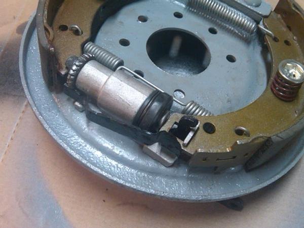
-
Dropping the propshaft out and rear brake cylinder
RichardS replied to RichardS's topic in Drivetrain & Rear Axle
Ah ... That explains why we can't slide the prop shaft apart. It's not a problem as you say, we can tie it out of the way. I've just looked at Rimmers to see about ordering some new brake parts and there is something called an H-Tappet which I don't have fitted to either of my rear brakes. I wonder if this has anything to do with shoe location? I'll do some further online investigation. Many thanks Richard -
Dropping the propshaft out and rear brake cylinder
RichardS replied to RichardS's topic in Drivetrain & Rear Axle
The springs are not that strong and are some way down the shoe so not exerting such a great force at the top end. I'll probably buy new ones anyway as I think I'll replace the slave cylinders as one of them was seized and I've had to refurb the piston. In the meantime, I think I'll try a spacer on the handbrake actuating arm as that will provide a positive end stop. Richard -
Dropping the propshaft out and rear brake cylinder
RichardS replied to RichardS's topic in Drivetrain & Rear Axle
I understand .... but the gearbox flange is still connected. It's the actual diameter of the propshaft which is wider than the gap between the frame rails. We could pull it out under the diff if the splined section would come apart but it doesn't appear to. Richard -
Dropping the propshaft out and rear brake cylinder
RichardS replied to RichardS's topic in Drivetrain & Rear Axle
Thanks Pete We've removed the exhaust system. It sounds as if the prop shaft is supposed to be wider than the the chassis rails which seems incredible but it is what it is but it does mean that we can't simply leave it hanging down out of the way. Is there a snap ring on the splined joint as there's no chance of sliding it out under the diff if we can't slide the joint apart? The brake shoes and the springs all seem to be in the right place but the middle locating spring is not sufficient to stop the top of the shoe sliding off the smooth button. The large spring between the two shoes at the top is not really exerting a force in the plane required to stop the shoe sliding off. In fact, it is probably making it more likely. The only thing I can see which would stop the top of the shoe moving outwards would be the hooked end of the handbrake actuating arm which goes through the rectangular hole in the shoe but the hook sticks out through the hole by about a cm which allows sufficient space for the shoe to move outwards. If the actuating arm was a bit shorter it would be a perfect alternative to the usual grooved piston but it isn't. I've stripped down and rebuilt brakes and removed prop shafts on dozens of cars over the last 50 years but it seems that Triumph certainly liked to plough their own furrow. 🙂 Richard -
Dropping the propshaft out and rear brake cylinder
RichardS posted a topic in Drivetrain & Rear Axle
Our work on the new Mk3 1973 GT6 continues, as does my confusion. I've been doing the brakes (they didn't seem very good!) and leaking diff oil seal today and have come across two issues which I've never encountered before so any help would be most appreciated. Firstly, the prop shaft. It seemed like it would be a simple job to drop/remove the prop shaft to access the oil seal. However, two issues have arisen. The prop shaft is too wide in diameter to drop between the chassis rails. Presumably this means that the only way to remove it is to remove the body and lift it upwards. I have never know a car where the prop shaft cannot be dropped downwards. Is this normal for a GT6? Our second thought was to pull the prop shaft apart at the splined joint and slide it out backwards. However, this doesn't work either as the sliding splines extend a couple of inches and it then locks suggesting that there is a snap ring or similar. We've not forced it as we can drop it out of the way enough to do the oil seal but should it simply slide apart. Secondly, the rear brakes shoes are self adjusting and there is a groove in the self-sdjuster which the brake shoe locates in. However, the piston itself does not have a groove but it simple a smooth "button" which the shoe appears to slide off and damage the rubber dust cover. I've never seen non grooved brake pistons before so I'm wondering if there is something missing on my car .... or do I take the angle grinder and fashion a groove in the button? Many thanks for any clues. Richard -
Do I need a different speedo drive pinion?
RichardS replied to RichardS's topic in Gearbox & Overdrive
Thank you all for your help. It's now clear that I need a 1152 TPM speedo. There are a couple of classic Triumph specialists near me that I'll pay a visit to but any other suggestions would be most welcome. I used to work in Carshalton with a Nigel Clark who drove a Spitfire in the mid 70's. Richard -
Do I need a different speedo drive pinion?
RichardS replied to RichardS's topic in Gearbox & Overdrive
Yes, my number is KE23600O although I didn't know whether that last digit was 0 or O but I learn something new every day on here. 🙂 From the paperwork I have going back to the early 1980's, the engine and body are still the original pairing so, yes, it probably came with an overdrive. I did notice that a few years ago the mileage on the MOT records suddenly dropped from 90k to 30k but it seems highly unlikely that someone did 40k miles in a year so I'm guessing that a speedo was fitted from a non-overdrive car. There's probably a receipt for it somewhere in the records but there is so much paperwork that I haven't had time to look through it all. Richard

