

Jim-GT6
-
Posts
76 -
Joined
-
Last visited
-
Days Won
1
Content Type
Profiles
Forums
Blogs
Gallery
Downloads
Store
Events
Posts posted by Jim-GT6
-
-
1 hour ago, ed.h said:
I added a port to access the speedo cable fitting.
The whole cover was a one-off. More pics here:
http://bullfire.net/GT6/GT6-74/GT6-74.html
Ed
Wow. What a project. What a floorpan too. Fabulous. I like the look you've got on the cover panel and that's a great seal. I aspire to something similar .... on an ABS bought one mind you.
-
8 minutes ago, clive said:
tried making a small hole into a large one with holesaws?
Hi Clive, that neat trick will only work if you're in the right place first go. You'd have to keep going bigger from wherever you started. Agree it would be very difficult / next to impossible to start a new location on ABS without a centre drill. It's too hard and skiddy. I don't think so bad on fibreboard though. With patience I imagine you could probably do it using the hole saw by hand, with no centre bit fitted. All the way through, or well enough started to finish with a drill. I'll report back if I try it
-
15 hours ago, JohnD said:
the gearbox filler is secured by S/T screws, into Spire clips on the GRP edges of the hole. The hole is not circular because my first drilling wasn't centred! I suggest a small one first, 1"? Enough to peer through while the filler is illuminated by a torch from below, check orientation and expand hole to suit.
Thanks John. That's how I was thinking to try and secure it too.
13 hours ago, dougbgt6 said:notice Dick and John's don't have foot rests, difficult to do with such large access holes. You godda have a foot rest for sophisticated motoring!
😂 I was thinking to remove mine! I swear it's why my non-moulded carpets sit so horribly in the footwell. I've currently got a buried footrest under a big pleat of carpet that gets in the way of the clutch! Doesn't fell very sophisticated 😁
12 hours ago, Peter Truman said:I use the female end of a 1/2in socket extension bar ie the internal 1/2in square loosly fits over the sq of the gearbox top up plug and I've drilled a in hole in the bottom of the sq socket of the extension bar and fitted a small magnet into it to hold the plug so I can extract and replace the plug without loosing the plug or having to use your fingers down a small hole
Thanks Peter. That sounds ideal. Think I've already got everything needed to copy your tool knocking about. I hadn't thought about extracting the plug without dropping it. Save a lot of swearing!!
1 hour ago, Stratton Jimmer said:I am now so adept at tunnel removal and refit that I can do either task in less than ten minutes.
Last time I did it (which was the first time I'd done it), I was about 2 hours each way! You could get a job in a pit crew Stratton!
Seeing all these pictures is super helpful. Now I've got a better idea of where to aim, I'm beginning to think I could try this in situ on my old cover without removing it, enlarge out from a small hole, top up my gearbox, do a fairly crude patch until summer, then rework with a new lined tunnel once the weather warms up. Doug - don't suppose you jotted down those careful measurements by any chance?
Prepping one off the car, rather than fixing up the old one, will also make it less of a big single job.
-
25 minutes ago, dougbgt6 said:
Jim,
Here is my tunnel. I have recessed lighting in one of my bedroom and bought an auger (?) to drill the holes in the ceiling, it also did the hole in the tunnel. I bought a giant bung on Ebay and sealed it with bathroom sealant. The tunnel is lined internally with SilientCoat. You'll notice there's a lip on the bottom and the front. which I think is there to increase rigidity, but because of it I had to double up on the rubber gasket with draught excluder. My brother repaired his cardboard tunnel with fibreglass, more fibreglass than cardboard now, not pretty, but functional.
There are 3/4 threads on here with other people's solutions.

Doug
That does look good Doug. Surprised the hole can be that small. Was expecting to need an access hole something more postcard sized. Did the tunnel, seal and lining make a big difference to the heat / noise / fumes?
Jim
-
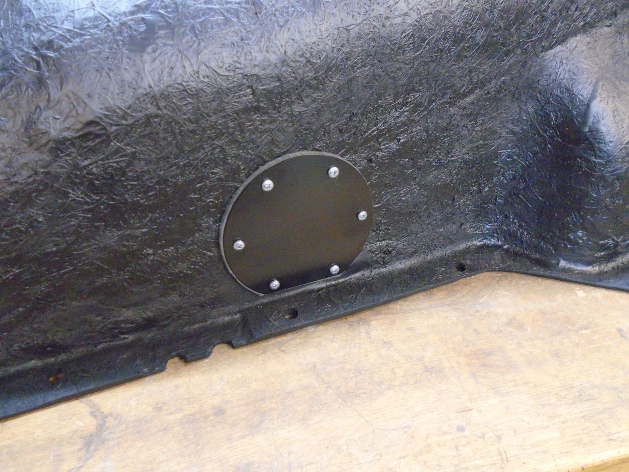
Hi folks,
Old thread I know, but searching for examples of access panels people have cut in their tunnel covers. Anyone got photos?
How to make it actually work? How did you choose to fix / seal it? Do you now just peal back the carpet on the side of the tunnel to reveal the cut access panel?
My tunnel is original type, and very weak /broken. Held together with gaffer tape at the top front upstand. No good seal. Just old bits of one. Had it out last summer for a clutch slave replacement. I read a good thread (somewhere) on how to strengthen and straighten the old type with glass fibre mesh and resin repair. The author was of the opinion that restoring the original type with this method gave a better outcome than a new plastic or GF replacement.
Early summer I plan to remove, repair, modify for access, get a good seal, and hopefully sound / heat insulate. I've seen some of the products - Dodo, Silentcoat etc. What did folk pick? Hoe tick to go? I see the 4mm (thick option) is suggested for tunnel covers.
Do folk put heat proof matting on the underside and more sound deadening on the outside? Or just one? I want to dampen the transmission noise primarily, and seal in the cabin a bit. A little heat insulation wouldn't hurt. The many missing grommets and poor tunnel seal don't make for good cabin air.
I'd be keen to see photo's of people's mods!
The split tunnel idea in the thread above is quite interesting. Would in to need to be cut into 3 parts though to avoid having the take out the H support etc.? If you were to make two cuts from front to back, either side of the mid line, you might be able to create a centre section that stays in place, and good sized side 'wings' that remove?
-
A second try at video. If no joy ... ho hum
-
 1
1
-
-
Ahh shame. It was a video. I guess videos don't work. I'll see if I can make a tiny one and try again. But, hey, it's 'fyi-fwi-vroom'! that's basically the video 😃
-
6 minutes ago, johny said:
Well done, but dont start thinking all jobs are going to go like that - you can easily get lulled into a false sense of your own ability😁
I'm quite keenly ware of my own limitations 🤤
That's why this is so noteworthy. One in a row! 😂
-
20 hours ago, Peter Truman said:
I was putting the full start load onto the ignition switch where as using the old solenoid meant that the load was as per original design
Hi Peter,
Sounds like you've got it well sorted for a good deal. I'm not sure I share your friend's worry about the ignition switch. I think it's the same difference, or, swings and roundabouts. As long as when the ignition wire is connected the onboard solenoid you take off the jumper wire, it's the same as the standard setup. Ignition wire to solenoid. Either bulkhead or onboard starter. With the jumper wire and bulkhead solenoid option (as we've both gone for) there is the possibility either one of the two solenoids may fail, and stop things working. So two potential failure points instead of one. I think ....
I wanted to keep things simple on the first pass, so opted to leave both active.
Easy to switch if the need arises.
-
1
-
-
Update on the outcome: job done and it went more soothly than I can believe! Delighted.
Up on ramps, as I hoped I may stand a chance of getting to the lower starter bolt from below. Knew I may need to remove tunnel cover if not. Once up, took off the cardboard side-valance rear bolts, and pulled the valance away without undoing the front mounts at radiator. As they're flexible, they're easy to manoeuvre. Pulled away with a bend and a waggle. They aren't cardboard I know, but what, fibre board perhaps? Anyway I'm a fan. Was tempted to look at aluminium, but don't expect you can bend and waggle the lovely looking aluminium ones as easily.
With the car higher up and the valance out of the way, I could see that I could actually get to both top and bottom fixings from where I was, not even needing to go from below, with a 9/16 stubby spanner on the rear side, and socket on the front. Disconnect the battery. Starter was off in a matter of minutes. Flywheel teeth looked nice and clean and sharp. Old starter not so good. May look inside one day.
Needed to know if I needed the spacer(s). Spec. given as a toleranced clearance, rather than mesh.
Distance from starter mount surface to closest face of flywheel teeth (distance to flywheel). 18.2mm
Distance from starter mount-surface to top edge of pinion (amount it sticks out) - I measured to the very top of the pinion, including the tooth chamfer i.e. the end face of the pinion gear, not the extent of the tooth face width, and ignoring the protruding stub of starter shaft: 23.3mm
Spacer thickness: 10.5mm (the actual spacer thickness, which excludes the raised ring, as that mates into the hole)
There were also two thin shim plates between the beefy spacer and the mount surface. Flat. Same shape as the beefy one. 0.5mm thick (each)
Position without any spacer: pinion would be in 5.1mm interference at rest.
With just beefy spacer, in 5.4mm clearance.
Haynes states the clearance needs to be 2.4mm to 4.0mm.
It was thankfully obvious that I needed the spacer, and that I didn't need the additional two shim spacers, as the clearance is a tad more than required with the beefy spacer alone. I say 'thankfully' obvious, as worst case is to be so much between-two-stalls that neither is gonna work.
I'm pretty relaxed about the 1.4mm additional clearance, particularly as the standard starter is referenced to the chamfered face of the fly-wheel, resulting in less contact face width (the old starter pinion has chamfers on it as well, so there are two chamfers reducing the face contact width when the pinion comes in from the back). The new one comes in from the front and there is no chamfer on front face of flywheel, so I've probably got more face-width mesh AND more clearance than the standard starter would allow. The chamfers are each a good couple if mil. I've got one less chamfer.
Kept the bulkhead solenoid in circuit, and used the supplied jumper wire between starter main terminal and the on-board solenoid socket (effectively disabling the onboard solenoid I guess). Nuts were tight all the way off, so wire brush and copper slip. Hole in original ring-terminal on the cable was a fraction too small for the new starter post, and a replacement that did fit was in the kit. Had plenty of cable, so cut off the old ring terminal end, plus a bit, to get back to fresh copper, stripped and fitted supplied ring terminal, including heat shrink. Managed with a lighter. I have no power out there. One Father's Day I'll ask for a battery powered heat gun. Vaseline on all the connectors.
The cable could so easily end up pressed against the exhaust manifold if not routed to bend the right way, but it's so chunky you can get it to a happy shape and it'll stay.
I'd previously rotated the starter mount plate one hole from a first looksee, and that proved worthwhile. The lump is now sat pretty equidistance between chassis and steering column. A good 30mm clearance above and below.
Reconnect battery.
"fwi-fwi-vroooommmm!". It sounds like a modern, and it sounds way more refined!
The three sounds I could expect before were either: "CRANGWAARGARRGGARRRZRAFFERGRAAH!!!!!!!!!!!", or "click ..............", or "berrrrrrrrwumm .........berrrrrrrrrrrwumm ....berrwumm ....berrrrrwumm ....berwum..berwum.. vroooommmm!".
I'm going to see if I can upload a video capturing the new audio here. Not sure if I can.
Once I knew it was all good, thanks to the experience of Colin and Steve, I put a generous glob of thick silicone sealant over the rubber grommets that are uppermost on the starter. It will bond them in, and seal them far better (they don't feel that tight in there). Maybe it will give me the same 14 years of service as Colin's did, without the water ingress rebuild! Thanks both for the tip. Fingers crossed. I've got some Captain Tolly's sealant too (which I bought thanks to another tip from another Steve at the club) to stop my window seals leaking, but figured that would be a bad idea. It's super-low viscosity as it's designed to find cracks and gaps by capillary. It would likely work its way all inside the starter. Thick jam stuff seals over without penetrating.
So .... if you have got a GT6 Mk3, with a standard exhaust manifold, you MIGHT well be able to do this without removing the tunnel cover, or even jacking it up. Get the engine valance out of the way. Stubby 9/16 spanner on the rear, and a couple of socket extension lengths (or another spanner) will do the front side, all from the engine bay.
I can't believe how well it went. There is usually SOMETHING that goes bad, or something you come away knowing you've buggered, but not this time. Two hours end-to-end. Well three. Including two tea breaks because I couldn't believe how quickly I'd got to milestones! Copper slip, vaseline, silicone sealant, new crimps and connectors, known clearance that's pretty-well to spec. Would have always worried, if I hadn't measured, that the engagement could be tiny. Just a couple of mm mesh would probably work fine and sound fine at first, but wear the edge of the flywheel teeth and put a lot more radial load on the starter shaft / bearings.
Thanks everyone so much! 😃
I mean even the weather was good. Jeeeez. Might go and bet on a horse or something.
-
1
-
-
1 minute ago, Iain T said:
We don't so much drift but steer full steam in another direction....it's one of the joys of this forum!
I had that when I got the car. Turned out to be a dodgy rear shock and old tyres 😁
-
 1
1
-
-
5 hours ago, Iain T said:
Sorry for thread drift.....
Guys you're killing me! 😂
I haven't even taken a spanner to the car yet. I'm likely to need to come back on this topic. At least to give and update on the outcome!
-
WOSP have a useless website for technical info. I can't confidently identify which of their starters I've got, as the part numbers on the box aren't listed on the website, neither is my car, and all the starters have one common fitting guide to download. Same as the one in the box. No data sheets. Not very impressed.
This unit is designed as Pete describes. The leading edges of the gear teeth are chamfered two ways, and the helix is driven in by a spring with a cap on. I think. I read this prevents any clash, but I can't remember where. The faces of the flywheel teeth are flat though, and you could hit them wrong. I guess you might get a single click and need to retry if it needed to tick on one half tooth? It may not need to though, as I could easily imagine the torque applied to the gear through the spring cap as the unit advances and the spring is compress and twisted, could slide it round enough to slip past the leading edge.
-
5 minutes ago, Ian Foster said:
I couldn't so had to take the tunnel out again (whoopee!)
😣
I'll allow more time then! Oh well. Another chance to check the gearbox oil.
-
2 minutes ago, Colin Lindsay said:
Here's the offending drain hole that let water in,
That hole is exactly the same on mine! It has a rubber bung in it though. Did yours fall out? I guess I might be wise to put silicone around it once I know all is well.
-
Looks like I'll be measuring. I expect it should be quite easy to tell by doing a measure from mount surface to flywheel teeth. The spacer in question is pretty chunky, so it will hopefully be obvious if it's needed once I know the distance. Mine starter does look a lot like Colin's.
Ingress issues seem to be a common experience .... 🤔
-
Paddock's think it's a straight swap in place of the original, meaning just change the starter and leave any spacers in place.
The fact the GT6 employs a spacer as standard to make the starter offset correct suggests to me that the distance might be dictated by a standard / common throw distance of starters perhaps? The new starter fits many many other cars. I would think those cars may or may not have spacers depending on whether they need them to match a common starter spec. If that's so, you'd expect to have to reuse any (standard) spacers you find on any car. Or at least on any car on the list of cars it claims to fit?
Of course that line of thinking may be complete twaddle.
Photo's of Colin's absent spacer suggest that reasoning is unsound.
-
2 hours ago, Colin Lindsay said:
check for any small drain holes that would be in the lower side, but are now on the top, and block them with sealer or a grommet.
Thanks Colin. Wouldn't have thought to check that.
The photo shows what will be the top view. Looks rather like yours. Couple of rubber bungs there. Nothing on the other side. I would have thought they'd have put the labels on the 'top', meaning this orientation would be the intended one, but perhaps not. I'll certainly make sure I don't lose the bungs!
I don't have a spare engine knocking about to check mine with
") Your pictures certainly show the issue for that starter. It's not exactly the same as mine, but similar.
Your pictures certainly show the issue for that starter. It's not exactly the same as mine, but similar.
Paddocks aren't answering the phone. Hope I catch them before 4pm.

-
1 minute ago, Pete Lewis said:
fitted one to my Vit6 with a631 manifold that can get things a bit close but with a std mani you are fine
seem to remember you must keep the original spacer
battery is not a problem these motors take so little load compared to the bendix unit it will fling the engine over with very little in the battery
you will be amazed how much quicker these are
Pete
Thanks Pete! You are a legend. You've been helping so much on my steering questions!
I figured the same - battery is in very good health, but the standard starter is a big battery demand for any battery when it's minus 3 degrees. Figured the high torque option would be way more robust for very cold conditions when the voltage is low.
I thought same about reuse of the standard spacer. Might call Paddocks to confirm / see if they know.
-
Hi all,
I have a shiny new high-torque starter on the kitchen top ready to go in. Just posting to see if anyone had any tips or watch-outs?
I went for the Paddock's one:
https://www.jamespaddock.co.uk/starter-motor-hi-torque-2
It's a Wosp unit, with the mount plate supplied drilled with an array to allow multiple rational mount positions. Unused holes are covered over by a blanking plate between starter gearbox and mount plate, that has just a pair of holes. It has an on-board solenoid, meaning you have the option to bypass the bulkhead solenoid and go via starter solenoid instead, or keep bulkhead solenoid and add the included jumper wire to the starter, bypassing the onboard solenoid.
I'm planning to go with the jumper wire bypass option and keep the bulkhead solenoid in circuit. Thinking I can bypass the original solenoid later if it develops a problem.
I offered it up and chose to move the rotation one hole. Brings the motor lump pretty horizontal, with terminal accessible from top, and I think it will create roughly equal clearance starter / chassis, and starter / steering column. Looks like quite a bit of space available on my GT6 anyway, so don't think it will be close to anything. The high torque starters are smaller, and a different shape, and the shape looks to suit the space well.
I've had a look, and I THINK I can get to the rear side of the starter fixings without removing the tunnel cover. I've tried and can just about get a stubby spanner on the back side of the top bolt (rear side of bell housing), and I think I'll be able to get to the back side of the bottom one from the underside. I have a standard exhaust, which might help?
I watched a Utoob of a chap fitting a high torque starter to a GT6. He didn't like the price of the recommended one (and I can very well understand why! ouch), so he went for something from a Subaru or similar. He then had to check the engagement and clearance pinion to fly wheel via paint on the pinion (if pinion is the right term) run, remove, inspect, measure. He then had to have a new spacer plate machined to make the Subaru starter fit. I don't know if the saving of using a different starter option worked out well for him in terms of cost and hassle!
Question is - if I reuse the spacer plate already on the car, is it the case that I should expect the Wosp unit will then have correct amount of engagement and clearance to fly wheel, or do I need to measure things first? I guess I could ask Paddocks this question.
I ploughed on into buying the high torque unit without polling opinion here (possibly unwise), and I suspect some will feel I've just blown a bunch of unnecessary cash. You might be right. I ummmed and arrred. The GT6 is my daily driver. I have no garage, and it needs to start at 7am in January. I suspect that a fully standard system with everything in tip-top shape might deliver the reliability I need, but to do that, I think I'd end up replacing many associated parts (battery, alternator...) as they are both only just up to the job for winter night time driving, wipers, dipped beam, heater fan, stereo brings running voltage at battery down close to battery voltage. i.e., only just maintaining. 28A alternator and 330 CCA battery both feel rather under spec. Or only just up to task. There are 52A options and same type of battery with 520 CCA that I might move to as and when they need changing. But not now.
I've gone more with the idea that gradually uprating parts as they are needed for cold start, and hot running in blistering summer traffic jams for that matter, will add some extra capacity for everything when weather extremes present a challenge.
-
1 hour ago, dougbgt6 said:
Hi Jim,
Didn't realize this was you! How did I miss this thread?!! I have a ball joint splitter, somewhere. I'll dig it out.
My GT6 was 5 years old when I bought it, the trunnions hadn't been oiled since it left the factory. Vertical link snapped shortly after purchase.
As said just pump oil through till only oil comes out. When it gets a bit warmer worth taking the trunnions off and inspect the threads on the vertical link
Doug
Thanks Doug! Might come in handy. I figured I can't be over relying on my kindly AO.
New wheel nuts arrived btw. I'll return your spares! Thanks for the loan.
-
2 hours ago, Pete Lewis said:
clouting the hole makes the taper pin jump out so easily
I can picture clouting the Tie Rod upward, but clouting the 'hole'? I'm confused where to clout. What hole?
I'm hoping Doug might have some luck finding that ball joint splitter, although Wagger's method on the unscrew and mark option sounds very doable.
-
1 hour ago, Wagger said:
Just got back from visiting disabled brother.
You would be wise to mark your tie rods and check as advised. AND, yes, the trunnions should be oiled with Hypoid oil which is yellow metal friendly. Some greases and oils are not, and greases block the oilway. Grit sticks to grease and can act as grinding paste. In oil it should be more mobile and end up in the bottom of the trunnion.
Sorry, I see you said earlier that I could either wind out the tie-rods OR disconnect the tie rod end from wheel. I'll go with the latter. 👍
-
21 minutes ago, Wagger said:
trunnions should be oiled with Hypoid oil
Thanks Wagger. I was wondering about the oil. I've got EP90, so half way there. Just need a second grease gun. I've got my Dad's Wanner Gun, but it's full or grease obviously!
To check the range of free movement, is it easy to disconnect the tie rod end from the wheel rather than wind out the tie rods? Figure I would run less risk of cocking up on reassembly?
I can check em both, but is there a way to predict which trunnion will be potentially running out of thread given the tightness is at full right lock? Would that indicate whether it's NS or OS? If I understand correctly, one trunnion winds in while the other winds out, so which one winds in when you turn right? Try saying that sentence fast!


Another reason to remove the transmission tunnel - and how to avoid it
in Gearbox & Overdrive
Posted
Thanks Josef, my paper copies only go back to June last year. Andy is in my area. We both go the monthly meet. I emailed him and these are his articles. They are very handy: