

Stuart R
-
Posts
38 -
Joined
-
Last visited
-
Days Won
2
Content Type
Profiles
Forums
Blogs
Gallery
Downloads
Store
Events
Everything posted by Stuart R
-
Whilst gathering my essentials last night I noticed Aldi were doing a cut-to-fit boot floor liner. Not sure how long they'll be on sale for. My Herald's rubber boot mat fell apart years ago, and I've never got the measurements to hand at trade shows where they sell mat on the roll, At 3.99, reduced from 5.99, it seemed worth a go. It looks promising for a Herald. So long as you don't mind it sitting slightly offset so it reaches the off-side, and leaves a gap under the fuel tank. I've left it to 'rest' and flatten out and will return to trim to shape another day. Keep safe everyone. SR

- 1 reply
-
- 3
-

-

-
I'm getting 123cm. Hard to hold both ends of the tape measure and read though. I have a 4-5mm gap each side between the boot lid and tail light trim, but the lid still catches the chrome strip on the LHS. (Actually, bit sure how valuable this info is. This is on my Herald 12/50 Convertible in the garage. It has had the top of a convertible rear tub grafted onto the original wings at the spot weld seam - I wonder how accurately this would have been done.)
-
If anyone wants a chance to own a nice copy of the "AA Book of the Car", there'll be one coming to Duxford this weekend.
-
My dull drive back from the coast was brightened by the sight of a red Herald convertible last night, heading East around 7:30pm (Sun 19th Aug). I flashed my lights and waved from my grey VW Golf, wishing I'd had the nerve to take my Herald instead.
-
I like the "bed-frame". I might have to do similar for my Herald Convertible. How heavy is that rear tub, an easy lift for 3? I got through three angle grinders for my Herald restoration, but at least they managed to last beyond their warranty period! What I'm enjoying about your resto is that nothing seems to be in pieces for too long - hopefully it'll be ready for some summer motoring. Good Luck, Stuart.
-
I took my Herald's headlight bullet apart to clean it up and the internal coupler fell out in 2 pieces, so it looks like they can fail mechanically over time. Replaced like-for-like with new items that are still available from mail-order auto electricians. The soldering can be fiddly, but they look original. I then wrapped the completed junction with self-amalgamating tape to keep out the road spray. Good luck, SR
-
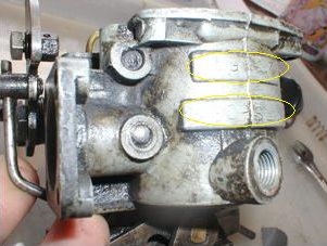
A bit too late here to help you, Colin, but might be useful to others. The ID marks on my Solex B30 PSEI are stamped on the float chamber body, but barely readable.
-
I bought mine from Rimmers in Lincolnshire earlier this year. It's not pretty but it fits. Be wary of buying better looking items at fairs such as Stoneleigh. I spotted a lovely new, chrome, lockable cap up there and was assured by the vendor it would fit. Got it home and it didn't. Obvious when you look at it, you need 3 tabs on the underside, not just 2. To be fair, it was a stall of general motor accessories rather than a Triumph specialist and they did refund my money.
-
My Herald 1200 went through a phase of refusing to idle, but ran OK with the accelerator in use. It's got the Solex B30PSEI Carburettor. There's a brass nut at the top of the carburettor, facing out towards the bulkhead - The Pilot Jet. If you find Solex technical leaflet 878 on the 'net, it's item 12. It had worked slightly loose and must have been upsetting the idle mixture. I discovered this accidentally by poking it with my finger and all came good. Confirmed my theory by placing a large blob of Blu-tac over it. For some reason the head was quite mangled and better carefully tightened with a socket/spanner than flat blade screwdriver. I'm not an expert though!
- 36 replies
-
- 1
-
-
- Carburettor
- Low power
- (and 5 more)
-
Hello Pete & Dave, I will try to take a closer look when time allows, the play definitely seemed to be between the Trunnion & Vertical link. I'm going to gather a few new fixing bolts together first as the ball joint's nuts and bolts were hard work to separate - don't want anything snapping. Thanks for your kind offer Pete, will keep you posted. Stuart.
-
Thanks Pete & Doug, the whole assembly tilted towards me at one point, so I know there was freedom in the trunnion through-bolt, but once the vertical link was upright, I could still feel this play, so that would point towards thread-clearance. In other words - worn? Had a look again tonight, with the front end jacked up - can't see any movement when levering-up under the road wheel with a stout plank of wood. Probably think it's spanners out again on my next day off.
-
Can I ask another Trunnion question, please? This weekend, I had to replace the upper balljoint on my Herald's front suspension. The gaiter on the ball joint had split and turned to a gloopy mess. With nothing holding the vertical link at the top, I was aware of quite a bit of play in the trunnion when trying to re-assemble the top joint. This was not apparent when the suspension was reassembled, nor at the MoT last week. Is this just due to the coarse thread used, or does it sound like I need to strip it down and inspect? Not that impressed with the modern replacement ball joint I fitted and hear similar stories about new trunnions. Thanks! Stuart.
-
Seeing Bordfunker's reached the stage where he's contemplating replacing his boot outriggers, I thought I'd try and replace the thread I put on the old lost forum about how I got on with mine. I've been meaning to replace this lost material for some time. I can't guarantee it's the right method, but at least it gives someone an idea of what's involved. This goes back to the Summer of 2009, so I can't remember every small detail. My outriggers were full of holes and it seemed it would be a more effective use of time to make the 4 lines of weld and replace the outrigger rather than attempt a variety of patches. Pictures are of work on the the off-side. Whilst the outrigger was removed, I made repairs to the corner of the boot floor where the rot sets in around the outrigger mounting point. Before work commenced, I made a notched wooden prop and placed it under the over-rider bolt tube in an attempt to keep the boot floor at a constant height throughout the work. Obviously, the rear chassis was supported on axle stands throughout. I bravely made a hacksaw cut through the old outrigger, around 10mm away from what looked the original factory weld. It was obvious at this point, when trying the new outrigger for size that I needed to take off more of the stub left on the chassis. There was also a metal 'tongue' visible inside the stub. I started taking of a little more of the stub, just a bit at a time, you can't put the metal back! After a bit of cutting, I was a bit shocked that the metal tongue gave way, but at least it allowed the new outrigger to slide nicely into the stub remaining on the chassis. I assumed the tongue was the remnants of the original outrigger, but don't know if that's true. Now with the outrigger able to slide in and out of the stub, I found the right position by bolting it into place on my newly-patched boot floor. Here is where errors may creep in, although I'd made cardboard templates, can I guarantee the holes in the new boot for are 'exactly' in the right place? And where did the outrigger bolts sit? Right in the middle of these holes, or up to one edge? I can't remember now and not sure I could remember then either! Anyway, with it bolted in the correct position to the boot floor I could see that a weld on the underside and outside of the chassis would be relatively easy. On the inside of the rail, I just had to take a few more mm of the old metal and then found a point where the trimmed edge met closely with an angled tab at the end of the outrigger. I had to up the welding power and move the MIG torch from side to side to ensure I made a nice weld and looking back at these pictures, maybe should have moved a bit more slowly for better penetration. There is just enough room with the rear wheel removed to get the MIG torch onto the top of the rail for the final weld, however it was done more by touch here (feeling the wire touch the join before pulling the trigger) as with the torch in the way, you cannot see what you're doing. Hope this may be useful to somebody! I've left a full rundown of my lengthy Herald project work in the Blogs section at the top of the page. Stuart.


-
Karl, I'm impressed with the speed of your progress. I've been at my Herald since 2003 and although now roadworthy, it's not finished! I've been there with the seized over-rider bolts and without an air saw, spent days in the boot using a very short off-cut of hacksaw blade to work my way through the bolts! My boot outriggers were full of holes, patching would take longer than the 4 lines of welds to fit a new one, so I asked on the old TSSC forum for advice. I got plenty of help, so as a way of thanks I then submitted a few photos of how I did it. Can't say the method is right, but it worked for me*. The words are lost, but I still have the pictures, so will try and put them up later in the chassis section of the forum. Regards, Stuart. *I'm sure this isn't why my door gaps are too tight.
-
Steve P was right, there are two top-hat shaped brackets on top of the narrow part of the chassis by the propshaft. The seat belt 'eyelets' mount through the floor into captive nuts on these brackets. I thought I knew the chassis of my Herald quite well, but clearly not enough. I double checked my workshop manual which describes Body Adjustment requiring slackening of bolts D,E,F,G,H & J when referring to Figure 1. Nice and easy, but Figure 1 has nothing marked G and no reference to seat belt bolts either. Sprayed some WD40 on these seat belt mounts but will have to return to this in the future. If I need to add more packers, I will run out of thread on the outer rail bolts. I think I bought 3" set screws on a like-for-like basis of what was removed. I notice that a new body mounting kit brought from Stoneleigh has 3 1/2" ones. That should help. Thanks for the tips. It'll be a while before I can report back.
-
Done those, Pete, but it's good to check the obvious! Should also add this is a saloon and loosened three nuts that hold the roof onto the rear deck too. Thanks, Stuart.
-
I never thought of that one, thanks for your thoughts Steve, will check that out tomorrow.
-
Hello, I'd like to improve the door fit on my Herald - it gets an advisory on the MoT every year about the sticking doors and I'm sure things are getting worse as the rubber packers deform. I've armed myself with the Triumph slide show notes on body alignment and Scans 1-4 from a recent thread here about door alignment. All notes seem to be about getting the door fit right by adjusting the tilt of the scuttle and rear tub with packers. Certainly the angle between drop glass and B post suggests the rear tub should be raised at the rear, but surely the fore/aft position of the rear tub will come into play to some extent? My door is a close fit all along the quaterlight-to-windscreen channel and is rubbing the paint inside the door frame on the B-post. I've got the door set as far forward as it will go. I can't help but think that sliding the rear tub backwards would help a little. I've loosened the 8 screws along the floor join by the front seats, the 2 on top of the axle 'hump' in the boot, two in each corner of the boot floor and removed the 2 bolts on each side side rail that join to the rear tub. I've released the handbrake, but not disconnected it. However, every time I try to gently jack up the body to insert packers, the chassis seems to come up with it. A lot of jacking only opens enough gap for a flat washer, rather than a rubber packer. Am I missing something? Should it be possible to separate the two with minimal effort, or do I need to be more brutal? I don't want to start bending the floor. I've tried levering gently with a bit of wood between chassis and rear body but all that seems to do is move the chassis downward. Maybe tomorrow's job is to try this again with the chassis propped on axle stands. The car has had a lot of bodywork done by me but to my knowledge the chassis and body has never been separated. I've replaced all outriggers and outer rails as well as various critical bits of floor around A and B posts and boot floor, so the chances of things meeting workshop measurements will be are minimal. However I do know that the body is no longer welded to the side rail on one side as it was when purchased! The worse side for door fit is where I've done minimal repair work. Any pointers welcome. Thanks! Stuart.
-
I'm not aware of a repair section for the upper part and can't recall a repro part being available either. I think it extends to the over-rider mounts, so would be a long job to replace the complete unit. At first, I thought my Herald was rock solid in this area, but then discovered these boot floor wells had been filled 1/2" deep with a Mastic substance. I think that just trapped the moisture in from below, the result is that although the floor in that area was rotten, the curved pressing on top remained intact. Impressed by your efforts so far! Stuart.
-
I bet this would be an expensive audio solution - a Marine radio unit with hideaway electronics and round control panel - can't see any dimensions for the panel but it looks bigger than a Smiths gauge. https://www.fusionentertainment.com/marine/products/stereo-units/ms-bb100 Searching the web for Marine Radio MP3 players seems to bring up quite a range of circular-mount solutions, but the smallest I can see is 9cm diameter. If you wanted to swap positions of the tuning and volume controls, maybe the leads on the "Retrosound" range of radios/Bluetooth players are long enough? http://www.moss-europe.co.uk/retrosound-radio-model-2-chrome-230-380.html No connection or experience with any of these products or traders, just some thoughts which might help. In crackly old AM days, the Courier Mini Mate was an on-dash, rather than in-dash solution. http://www.worthpoint.com/worthopedia/vintage-1960s-70s-mw-lw-classic-car-489078436 Regards, Stuart.
-
Pete, you are not dreaming. There are two dimples on the Herald, in the B post on the rear tub, but can't see any corresponding dimples in the 1200 or 12/50's door. Not looked at the detail closely enough to ensure the dimples are correctly spaced/located for the anti-burst catch. Regards, Stuart.
-
I've just had my Herald's radiator re-conditioned by 'Commercial Services' in Luton. The new core is still 2 rows deep, but around 10 more tubes per row. It's a late Herald 1200, so uses the larger radiator. I too had seen pricey ones on an auction site - £600! I was warned away from un-branded auction purchases as some are said to only feature one row of tubes. This work cost under £140 and was turned round in a day. The radiator frame was thoroughly cleaned and painted, so the Stanpart and Coventry Pressing Company badges are retained and clearly visible. Re-fitted last week, but not had chance for a road test yet.... A very similar price was quoted by 'Kempston Radiators' in Bedford; their first question was "Is that a big or small Herald Radiator?" It turns out that they do a lot of refurbishment work for a local Triumph specialist, so know their stuff. Hope that helps, Stuart.
-
There's a picture of my 1970 Herald 1200's tank and pick-up pipe in this blog entry: http://forum.tssc.org.uk/index.php?/blog/16/entry-10-2012-2013-getting-a-bit-more-done/ 4th picture down, if of any use.
-
Is the tank's Main/Reserve lever in the right place? I've known the lever's detent mechanism to weaken and the springiness of the rubber hose moves the pick-up pipe away from where you left it.
-
These pictures may be of interest, although not directly related to Aidan's problems. I couldn't see the blue Main beam warning light on my Herald 1200 speedometer and was concerned that it would be an MOT failure. Instrument back lighting was OK and the main beam warning bulb was functioning. There are 5 bulb holes in the Speedo, 2 for dial illumination which are larger and correspond with a patch of black paint in the dial housing. You can see that a forward facing light source is mostly going to hit the back of the dial and go nowhere else. 3 holes for the warning light jewels appear to have plastic/rubber hoods fitted that degrade over time and turn to gloop. I don't know what the hoods originally looked like, but imagine they are there to stop the dial illumination 'leaking' into the warning lights. I've seen this on both my Heralds and in this instance the gloop had partially obscured the light path to the blue jewelled lens. I cleaned as much of the gloop off, making sure I kept fingers and cleaning cloths away from the painted dial. If I remember it was pretty solid and could be picked-off easily. Replaced these hoods with some silicone cable sleeving as thought even if it touched the bulb, it should withstand the heat. The silicone sleeving is braided and so expands a bit and didn't really grip the back of the lens so addded some black PVC tape to keep things in place and reduce any light transmission from the back lighting. Everything is quite dim, so I doubt that's an issue. The main beam lens is a very dark blue, so light transmission is pretty poor to start with. Regards, SR


