

BestyA
-
Posts
31 -
Joined
-
Last visited
Content Type
Profiles
Forums
Blogs
Gallery
Downloads
Store
Events
Posts posted by BestyA
-
-
-
There are spacers under the frame (yes I know these save the carpet when moving the seat) but these will stay out for now. And I am definitely not cutting any more holes 😁
-
Thanks for that (I assume you have a standard steering wheel?) So I have somehow lost 3 1/2 inches! I will remove the seats and make sure everything is as low as possible. I might be cutting a hole in the floor at this rate😁
-
-
1 hour ago, Mathew said:
Thought there was a bit of a slot to be able to raise the angle, will have to double check or is that only the later spitfire?
Thanks for your message - I think that is the late Spit but I have some investigation to do.
-
If I undo the clamp and pull towards me? (and I agree anything under the dash is a faff🥴)
-
Hi all hopefully someone can help me out. A bit of background - I replaced the steering column (PO had installed a dolomite column) with original. I also recovered seats Inc New foam. I only have clearance of around 4 1/2 inches - is this right? There is also a finger width of clearance above the column to the dashboard (I can easily get my finger in there). Is this right? Any way I can raise the steering column?


-
I will give them a call tomorrow and see if they wil👍
-
Thanks Chris, that is a really comprehensive answer. I think the seal that is fitted is certainly too deep and hard. It also is cut short around the striker plate i.e. not there at all. I think I will look at the DX73 and see what happens.
-
Looks like I have the wrong seal I assume this is a "P" seal I will get a DX73 and see if that cures it

-
Thanks, (Pete &Nigel) I will give them a call, (I need door seals as well). If I take the seal off it sits completely flat, so I am hoping the hatch isn't twisted. If I shim, would you shim the same side, on the hatch hinge or the roof hinge, or is it suck it and see?
-
I have a rear hatch that sits high on the bottom near side corner. I have seen others shimming the hinges? Any idea if this works or do I just have to live with it?

-
I definitely didn't do this little modification. But there is an idiot working on the car at the moment!
-
 2
2
-
-
Thought I would give an update on this. After hours and hours of trying to figure this problem out, having bought a new hazard switch and flasher unit, nothing changed.
I have then been painstakingly tracking down individual wires.....and last night a breakthrough, buried deep in the harness in the most inaccessible place above the steering column there it was - somehow in the past the RW wire (right turn) had been soldered to the RG wire (left turn). Cutting the RW and joining it back to where it should be has done the trick.
So lesson learnt, though I am not quite sure what the lesson is!!
-
OK thanks for that, new switch ordered from Paddocks, let's see what happens.
-
I have seen a few threads on the hazard and indicators and I have now joined the tearing my hair out club. I have changed the previous steering column from a Dolomite (as fitted by the PO) to a GT6, which has required some wiring changes – however I am stumped with the hazards / indicators.
I have got to the point where the indicators will work! - however, when the hazards are on only the left indicators work.
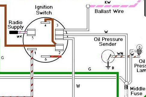
It is like the GW wire (as shown on the diagram) is missing – I have tried "jumping" the GW wire to the hazard flasher with mixed success. The hazards work but both right and left indicators work when indicating right or left or the indicators do work but the hazard light flashes at the same time.
Any ideas would be much appreciated.

-
Hi Jim, just tried it and it is the switch that gives it the spring.
-
 1
1
-
-
10 hours ago, ChrisJB said:
My GT6 Mk3 has four connections, numbered 1,2,3,5 on the Lucas switch (Pt no 1575A) as per the photo of the switch module in the original post. The Haynes Manual wiring diagram also shows a 5th connector numbered 6 that controls an anti run-on valve, this is not fitted to UK cars? The diagram states "Not all items are fitted to all models".
The Haynes wiring diagram also shows connectors 4 and 2 on the switch connected together on the switch confirming Doug's post.
That's helpful,I will see whether I can get the 4 to work.
-
26 minutes ago, dougbgt6 said:
I've replaced the original switch on my GT6 as the innards failed, I got the 5 way one. That small screw locks in the switch and there's a locating slot, the switch pops out easily. The wiring in the first picture looks scary
 there's broken insulation, it needs replacing. However, I wonder what's beyond the black tape, top right, hopefully the original correctly coloured wires? Which should make re-connection clearer.
Doug.
The wiring is scary, I have ripped out and replaced quite a bit of domestic wiring so far (and just found some more!) It's all been replaced along with a new 10 way fusebox, relays for the lights and rear heated windscreen.
The original colours are there as there are a number of soldered splices under the dashboard, my guess is that the 5 way combines 4 and 2 on the 6 way connector?
-
My GT6 has previously had the steering column changed to a Dolomite (by the PO), so the ignition and key position is in the "usual" position at the top of the column.
I like the inconvenience of the original GT6 ignition position (and want to revert to as much as original as possible) and have bought off ebay an original steering column with the key position down low (between the knees).
The current (Dolomite) ignition has 6 connections on the rear of the switch whereas the second hand one (from ebay) has 4 connections. Looking at the ones supplied by Rimmers there are 5 coonections. The wiring diagram says 6.
Questions are:
- Can I somehow use the 4 connection one I have
- Will the 5 connector version from Rimmer do the job
- Do I need a 6 connection version (and where do I get one)
- Also can I get a connection to the radio with any of these versions - on when key in position 1 (if that makes sense)


-
1 hour ago, dougbgt6 said:
GT6 servo only works on the front, so if only the front are locking up, it's the servo!
")
Doug
That's my line of thought now
-
Thanks everyone, looks like it is coming out for a bit of investigation.

-
6 minutes ago, Pete Lewis said:
to release any vacuum you can prise the plastic elbow/valve out of its grommet in the canister and realse vacuum from the canister.
have you checked the pedal for free play ??? very imprtant ....and cheap fix
Pete
No free play in the pedal, I will prise out the elbow and see what happens.
-
9 minutes ago, johny said:
strange to be a servo problem if theres no vacuum to provide the force... However its difficult to be sure that the vacuum has dissipated even after an hour as maybe your non return valve and system is really airtight?
I will start it up and see if they lock on again, then see if I can figure out if there is a vacuum there


GT6 rocker oil feed
in Engine
Posted
So I have the dreaded oil feed modification fitted by a PO, starving the bottom end and flooding the top end. Feed is teed off the oil pressure switch, so that is easy to remove. Question is how do I plug off the top end?