

JohnD
-
Posts
4,836 -
Joined
-
Last visited
-
Days Won
105
Content Type
Profiles
Forums
Blogs
Gallery
Downloads
Store
Events
Posts posted by JohnD
-
-
On 20/10/2023 at 17:21, JohnD said:
If you think that bonnet bulge is OUTRAAAAAAAGEOUS, Dahling! Wait until you see the new one!

-
 1
1
-
-
Ideas been around for a while: https://sideways-technologies.co.uk/forums/index.php?/topic/72-remote-clutch-bleeder/#comment-787
I was inspired by the Renault UN1 trans axle, where the slave is at the bottom! But comes with a bleed extension to the top - much more convenient!

Shows bleed hose attached.
-
Iain,
"raising the rear edge of the bonnet" to let out hot air? How does that work? On any car with a windscreen, there is a high pressure bubble just on front. Triumph knew this - that's where the intake is for the cabin ventilation!
Perhaps towards the edges??
John
PS "Anorak"?!?! I'll have you know I wear two T-shirts when it's wet!
-
2
-
-
On 19/10/2023 at 16:26, Iain T said:
How about a cod piece power bulge in the bonnet? I think it may effect the resale😂
Iain
If you think that bonnet bulge is OUTRAAAAAAAGEOUS, Dahling! Wait until you see the new one!
-
Early Heralds (and Spitfires?) had a header tank over the engine , an d no filler cap on the radiator.
Cut off the filler, get someone to weld a plate over the hole, and add a header.
-
Penetrating oil - Innotec Deblock. Works every time for me.
Heat - try to get the bolt stub RED hot. allow to cool, add Deblock!
Welding a nut on the stub - The thermostat housing is part of the water pump housing. Take off the water pump and you have something easier to carry and take to a garage or body shop. Ask them to weld a nut on for you, or else find a prper machine shop and get them to remove the stubs. If necessary the last will have no problem in putting in Helicoils to deal with damaged threads.
John
-
The Haynes manual contains a plan of this tool. Simple to make if you can weld.
It suggests solid hex bar (!) but I used 1" square tube, no probs.
John
-
 1
1
-
-
I fear that this won't suit you, IainT, but I had the same problem, caused by a too tall filler cap neck in a new copy Vitesse radiator.
My solution? Cut a hole, fill it with a beaten alloy dome, paint it a contrasting colour and make a bug into feature!

-
Bit of an aside, but a recent "Just rolled in" video on YouTube showed a modern, in for fitting a new carpet set, "because the owners son, short of money, had ripped them out and sold them."
Only in America?
-
1
-
-
-
In my OP, I remained positive about this venture, so while the general response seems to be the same with some reservations, perhaps I may be allowed to point out that I have been advocating that The Courier goes digital for YEARS! The TSSC has some obscure accountancy/fiscal trick which they argue kept the subscription down, despite the cost of issuing a printed version, and has used this as an argument NOT to go digital. Well, now they have gone digital, and Lo! the subscription goes up. Not that I think the two are at all associated - costs in general have risen recently, it's called "Inflation".
Many respected journals have digital versions - Octane, Classic & Sports Car, Car, AutoExpress, Practical Classics, etc.etc. to name a few. There are exclusively digital mags too, notably "Classic & Competition Car", which is extraordinary value for the range and scope of its text and pictures. Or it would be, if you had to pay for it, but when it is FREE it just proves my case! See: Classic and Competition Car Classic and Competition Car - Motorsport and cars of the past and present
John
-
For the love of the gods, TRY IT! I've proposed a simple fix. You've tried everything else, including things that just aren't relevant to excessively retarded ignition.
John
-
Just had an email telling that the Club has to raise it's subscription, sad, but I can't deny, necessary.
But I'm really posting about the next paragraph: "At last year’s AGM the Com proposed that we introduce an electronic membership to our overseas members, this was voted on and carried unanimously in favour." "An electronic member will receive a PDF version of the Courier magazine."
EXCELLENT! I'm sure that overseas members will be grateful to get their Courier more quickly!
Well done!
John
-
2
-
-

Your pic from above, niceguy, and it shows the distributor rotated clockwise from the normal position, which is with No.1 lead at 'six o'clock'. This I presume is the "Very advanced timing" that you have found necessary. But why, everyone cries!
The legbone's connected to the ... kneebone, or in this case the dizzie drive shaft is connected to the distributor drive gear and thereby to the cam shaft, and to the oil pump. The pump has a 'dog' on the end of its shaft that connects to the drive gear. But when assembling these parts, the pump must go in long before the others. Then when inserting the drive gear, the pump shaft must be rotated so that the dogs match, AND the gear must be inserted several degrees away from this orientation, as the hypoid cogs between camshaft and drive gear rotate the gear as it descends into place. The objective of this fiddly manoeuvre is to orientate the drive slot in the face of the gear to match the peg in the end of the Dizzie drive shaft, so that the dizzie is then in the correct orientation, with 1 at six o'clock.
Phew! A picture is worth a thousand words, but I can't find a diagram of all three (Pump, drive gear, dizzie) as they are always in different sections of the parts catalogue!
What I'm saying is that it is possible to assemble these parts in as many positions as there are cogs on the drive gear! That's 16, I think, so the possible error is in multiples of 20 degrees.
I suggest that is your problem, nice guy! Your cam mistiming is trivial, carb tuning likewise, neither could account for the advance you need to use. It's the Distributor! Take it out, look at the slot in the face of the drive gear. It should be in a "five past seven" position , but note, the slot is slightly offset, which should be to the left, thusly:
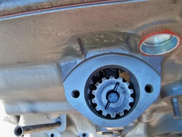
Alternatively, just move all your ignition plug leads one place counter-clockwise! Then re-time!
Simples!
John
-
-
OK, that disposes of 1/ and 2/ . Except that I note Gully's pic is of a GT6 and must be a rear wheel as there's a brake drum. If your seller has front discs and isn't a pre-12/50, 1962 then make sure they are the originals, Some non-original calipers are more bulky, eg Princess ones.
My point 3/, I stand by!
John
-
On safety, the Fb page "Triumph in Italy" have a copy of an advertising leaflet from 1961, for this 'rear seat' for a TR4.

The text says that "two children can sit comfortably and perfectly safe, because there are no doors that can open suddenly"!
How times change!
John
-
Nurse! The Chocolate Sponge Hat, a bib and a spoon, please!
-
4
-
-
Colin, Damned if I'll trust my life to a couple of U-bolts! A proper anchor should be a forged eye bolt as shown in my post above.
PeteH, Interesting RoT! What does it mean? The "removed material" for an M10 bolt would have an area of less than a centimetre squared.
John
-
57 minutes ago, nicrguy1966 said:
With the crank pulley off, I had a very good look at it, and there's no sign of any movement between the pulley and the rim with the timing marks. I'm even more confident now than at the start of the job that the TDC mark is in the right place.
OH!!!! Inspection is useless! Just as is resistance, if you are a prisoner of the Vogons. You cannot tell by looking if the inertia ring has moved! I have several examples to demonstrate this, on one of which the ring has moved by 60 degrees!
When you can, refit the damper pulley. Move the crank to TCD , as determined by a piston stop. THEN look at the crank pulley. If it coincides with the pointer on your timing cover, I will eat my hat (the chocolate sponge one), and resign from the Dishonourable Order of Gurus! Nothing else can remove the suspicion that you are trying to time the ignition from a fictional TDC point and I thought you had said that you had done this, and that the TDC marking and actual TDC coincided.
John
-
Fitting a seat belt anchorage point, that is secure and safe, is not complicated. Anchor plates, 55mm wide with a fixed nut, are widely available from respected suppliers, like this;
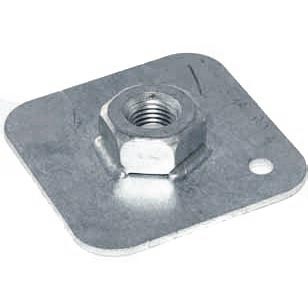
They should be welded to the reverse side of the panel, over a hole for an eye bolt of the correct size (7/16" or M10) and length.
The question is, will old panels have sufficient strength, in original manufacture or in their old and corroded state? A wider plate welded to the back with the above mount plate on top will spread the load even better. MotorsportUK recommends a 'counterplate' of at least 40 cms^2. This is 6cms square, not much bigger than the above mount plate, but go as big as possible!
Like this:

BUT NOTE! The eye bolt should NOT be mounted over the carpet!!! It should go through so that all the clamping force is on the panel.
ALSO!! The small hole in the spring clip should be filled with a split pin, to lock the clip into place
I can't find a better picture!
John
-
Three factors to consider:
1/ The Pitch Circle Diameter. Triumph used a smaller PCD than almost any other manufacturer, 3 ¾” (95.25mm). Do these wheels match that?
2/ The offset. This the distance between the hub mount and the actual middle point between the rims. Usually expressed as "ET" for "Einpress Tiefe" the German for offset. I believe that wheels with a 20-25 mm ET will fit.
3/ You may be able to find tyres to fit a 14" wheel that will clear the wheel arch. The new tyres will be radials and they will need to have narrower, stiffer walls to achieve that fit. Stiffer walled radials will reduce the footprint of the tyre by lifting an edge when camber doesn't stay in a small range around zero. This may be acceptable on a road car, it depends on how you drive it, but has been tried for competition where 14" wheels don't improve adhesion!
John
-
1 hour ago, nicrguy1966 said:
I only started down this route based on advice that incorrect cam timing could be the cause of my odd ignition timing.
Do you have other explanations for my need to have very advanced ignition timing? I am very open to new ideas.
I think I suggested a shifted outer ring (inertia ring) on your crank damper pulley, which was my first thought, but you found that it was a true indicator of TDC.
Other than that, it is possible to install the distributor drive 180 degrees out - the drive slot is only slightly offset - but that would need VERY advanced timing!
Now you have corrected this small cam timing fault, please try the engine and prove me wrong!
John
-


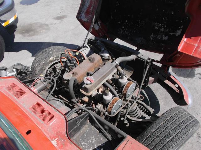
Radiator cap touching bonnet
in Bodywork & Fittings
Posted
After Thruxton this year, my old bonnet was marmelised, and while repair was possible, it would be a massive amount of work. A friend came to my rescue, and offered me a lovely, undamaged GRP bonnet (I am MOST grateful!) to which a DPO had added said outraaaaaageous bulge which to my eyes only made it better. They had also cut two holes in it and rather than patch them with GRP, which would never be an invisible repair, instead I searched for and found these blingey air intakes, big enough to cover the holes. Yes, they look as if I have a V-4 and supercharger under there!