

Bordfunker
-
Posts
1,005 -
Joined
-
Last visited
-
Days Won
17
Content Type
Profiles
Forums
Blogs
Gallery
Downloads
Store
Events
Posts posted by Bordfunker
-
-
6 hours ago, Colin Lindsay said:
Yikes!! That shaft has been eaten.
It’s not great is it!
You do have to wonder about some owners don’t you?
You’d think they’d appreciate, just possibly, that the manufacturer might have factored expansion into their settings!
Karl
-
Not a lot of progress since last month as Covid has paid a very unwelcome visit to the Bordfunker household, with all 4 of us going down with it within 48 hours.
That was over 10 days ago, and I'm only now getting back to some semblance of normality, so like I say, progress has been lacking.
I did manage an hour and a half in the garage this afternoon, as there is only so much lounging on the sofa with the hounds that even I can tolerate, so I made a start on cleaning up the pistons.
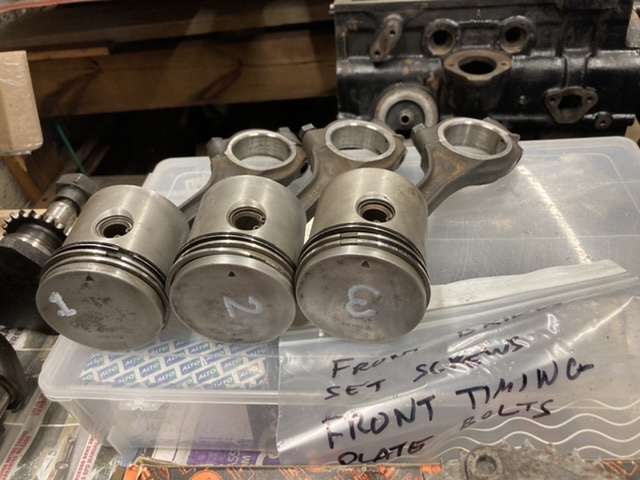
Just Gunk and a Scotch pad removed the baked on crud, following a quick blast with the steam cleaner, and a wipe down with an oily rag.
That just leaves no.4 piston to do next week, as cleaning pistons is not the most exciting activity.
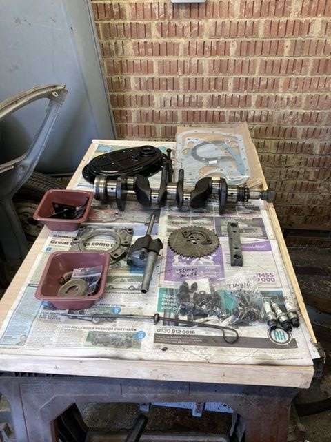
Having tried to drift out the pin holding the end cap on the rocker shaft, so that I could properly strip it, and check its condition, I gave up and drilled out the retaining pin.
I only had to drill about 4mm into it, following which it drifted straight out with a single tap.
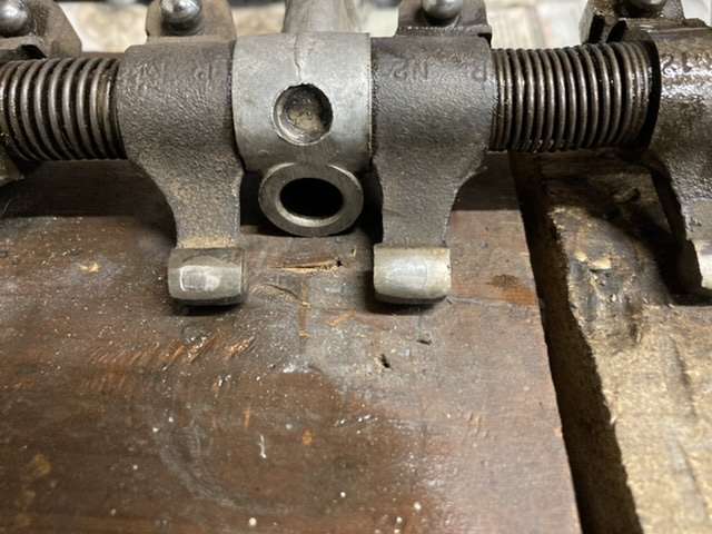
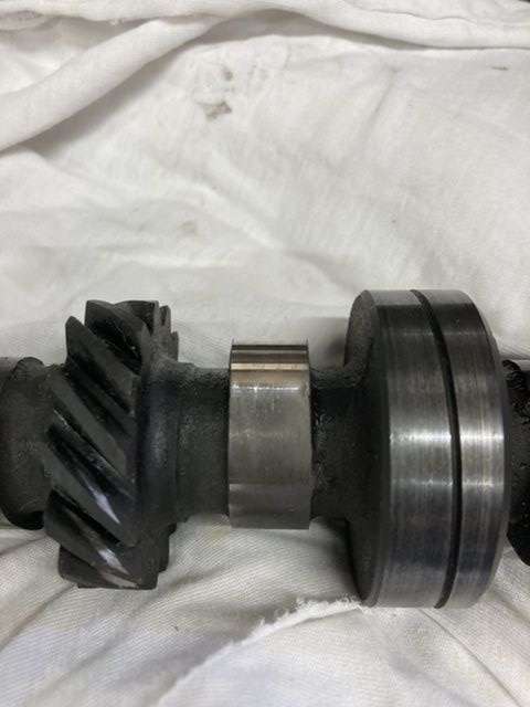
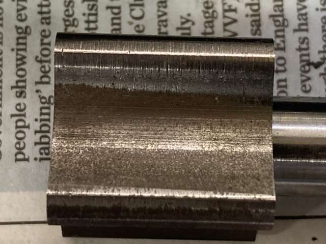
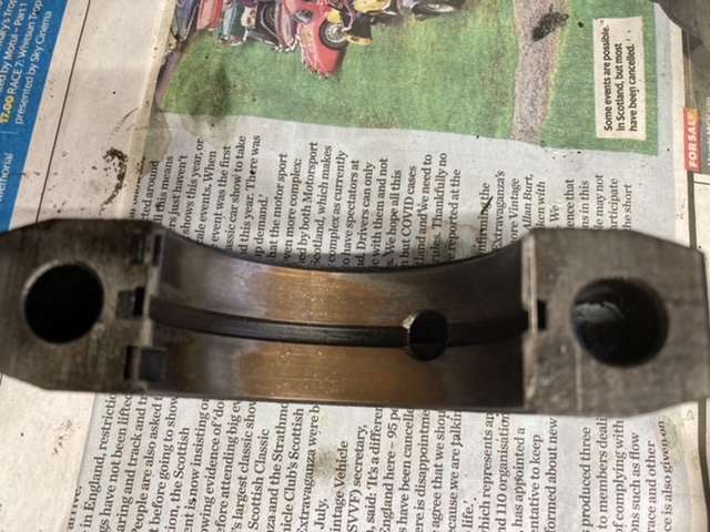
I am so glad that I did remove the end cap, as even rudimentary scrutiny, highlighted a number of deep gouges on the shaft itself.
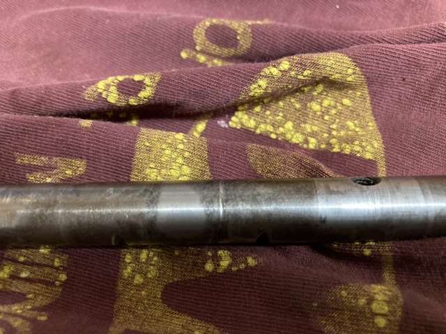
That's a gouge in the centre there, it must be at least 0.5mm deep, and it wasn't alone.....
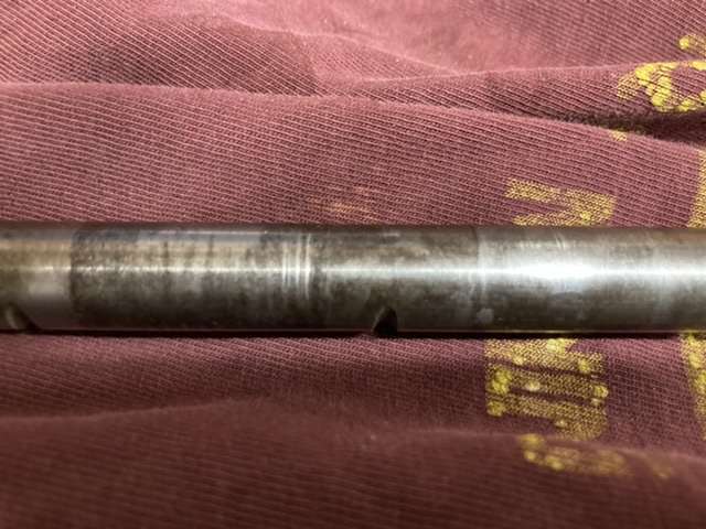
.....that's 3 gouges close together.
So that means the rocker shaft is scrap, as I'm not putting it back in in that condition, another part to add to the list.
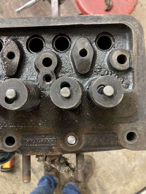
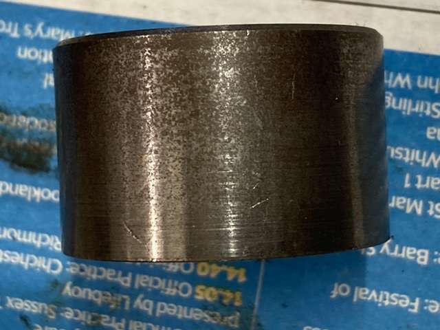
As for the rockers themselves, the photos below indicate the general condition
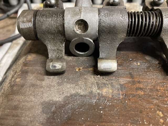
Those areas of wear are about 0.5mm deep, which suggests that they have probably worn through the area of surface hardening, and therefore I am assuming that these are also junk, and in need of replacement.
Fortunately Mick Dolphin appears to have NOS ones in stock.
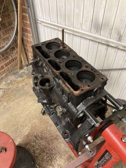
Aside from those discoveries, I also managed to remove the block from the engine stand, as, now I am feeling better, I am hoping to get it to the machine shop this week in order for it and the head to be checked and skimmed.
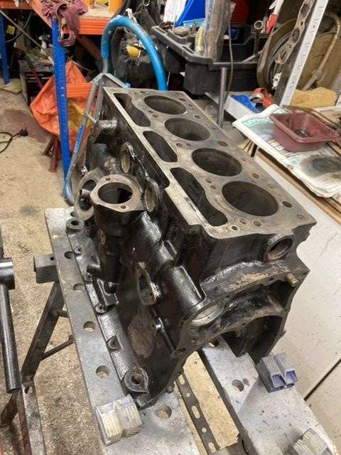
Which would be nice, as I can then look at putting the engine back together again, and then returning to the chassis welding, which is what I should have been doing.
Karl
-
 1
1
-
-
I bought a Polti Vaperetto about 10 years ago with the John Lewis vouchers I was given when I left ( I know! Go figure)
Managed to kill a washing machine with it, but it has been brilliant at blasting all the crud off of, and out of the Herald’s engine over the last month.
Just spray or brush on some Gunk, as Pete says, agitate with a brush, and then blast off with the steam cleaner.
I’ve found it takes about 3 cycles of cleaning to get everything really clean but that was the insides of a 50+ year old engine.
Karl
-
Thanks for the confirmation both.
New exhaust valves duly added to the shopping list. Luckily it appears that Mick Dolphin has NOS replacements in stock as well as the required new head gasket.
The valve guides themselves look to be good, with minimal movement of the valves when placed in the guides themselves.
I need to strip the rocker shaft down to clean the assemblies, and also check for wear on the shaft itself, however is the pin which retains the components on the shaft just supposed to drift out?
Thanks
Karl
-
All this work on the engine started out as a simple gasket and oil seal refresh, and has suffered continuous scope creep ever since, of which more later.
This weekend's activities started with a test of how gas tight the head was, by pouring white spirit into the combustion chambers, having first remembered to put the spark plugs back in, and waiting.
I used white spirit simply because I had it to hand on the bench.
Half an hour later, following a cuppa and a biscuit, no change, no leakage from the valves at all, so all good, right?
My valve spring compressor turned up on Friday, and almost immediately seized!
Cue gentle persuasion with a mallet and a soak in penetrating fluid, and then a couple of minutes of working the mechanism back and forth, and normal service was resumed. No idea what that was about, but glad that I was able to fix it, as it made removing the valves a doddle.
To make sure that I kept everything in order, I made myself a little rack out of some spare ply, and started loading the valves and associated components into it.
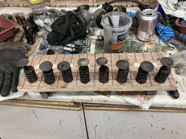
Note that this is the 'Dirty' bench, as if you couldn't tell!!!!
Now I was expecting collets when I removed the valves, but instead, I have these metal discs with a rebate that the spring sits in, and a figure 8 hole that locates the top of the valve.
No complaints from me, as this looks a lot simpler to put together than the fiddly collets I was expecting.
I mentioned scope creep earlier, and I believe that the exhaust valves may well be the cause.
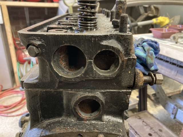
This is one of the exhaust valves pre-clean up.
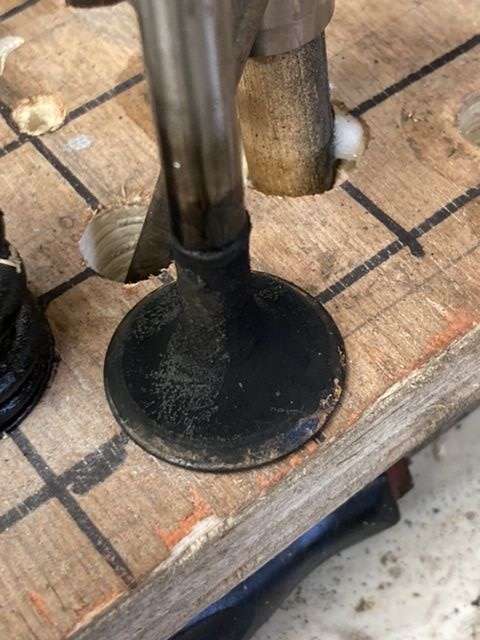
And this is it post clean up.
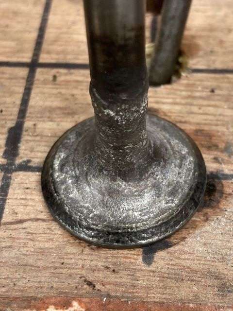
As you can see, none too pretty, with a lot of pitting around both the valve edge, as well as the base of the valve stem, so I am now expecting I need to purchase a new set of exhaust valves, as they are all in pretty much the same state.
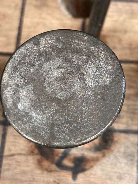
This is the underside of the valve head itself.
The inlet valves on the other hand, all look like this, far more healthy.
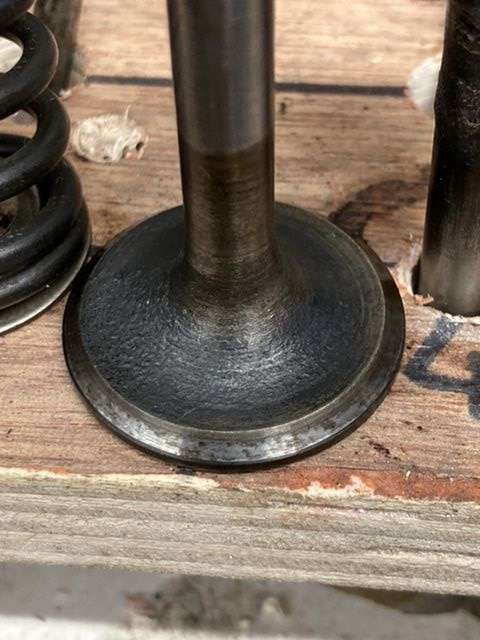
To my untutored eye the valve seats themselves look to good, but I would still expect to lap them in to be on the safe side.
Here they are.....
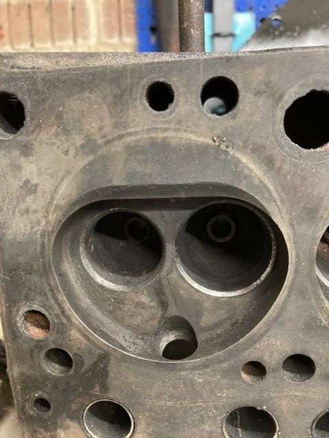
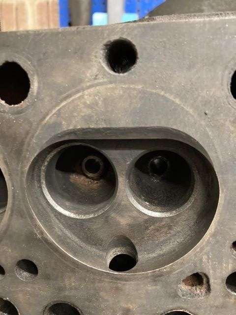
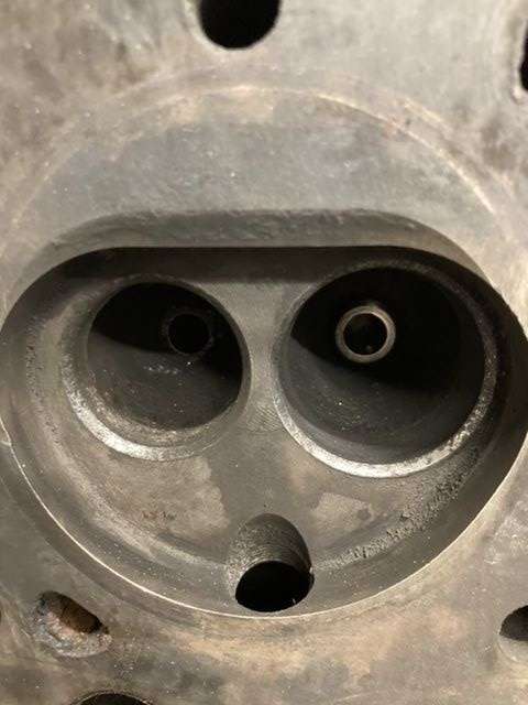
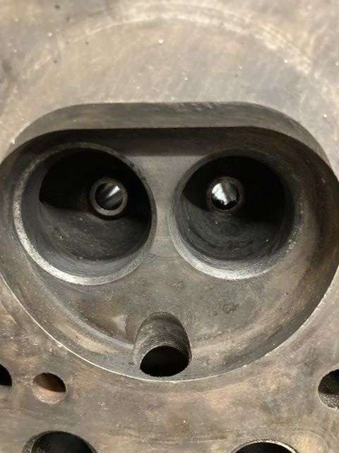
It would be good to get the views of the hive mind on the state of the valves and the valve seats, particularly as I am aiming to get the head and block to the machine shop this week.
Current expectation is that the head needs to to be checked for flatness, and if needs be, skimmed, and the block needs decking to remove some corrosion around a couple of waterways.
Let's see if that scope creeps a little further.
Karl
-
On 21/09/2022 at 08:35, NonMember said:
Do you mean the one the pump shaft runs through? If so, it's possible to drift it out but a pain to refit. Whether you need to depends on what work is done to the block.
Thanks. In that case I will leave strictly alone.
The valve spring compression tool turned up today, so I can start cleaning and stripping the head this weekend.
Karl
-
Steve, is that the one in Porthtreath?
I saw it earlier in the year when I was on holiday in Porthreath, and had to go and have a nosey.
Karl
-
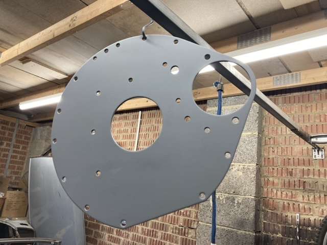
Pete, I did wonder about that as mine was partially painted, and I have seen a number that appear to have been fully painted by the factory.
The front plate was definitely painted back and front, but the backplate I’ll take back to bare steel where it meets the block.
Speaking of blocks I’ve found a place locally that can certainly do the head, but may not be able to do the block. While there is a place that can do both for £140 in Milton Keynes, which seems fair.
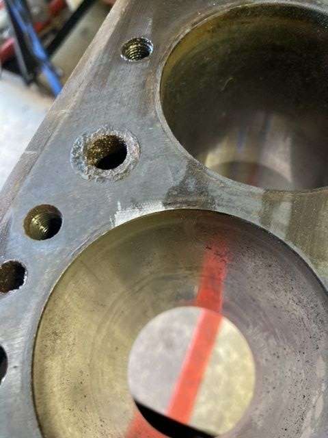
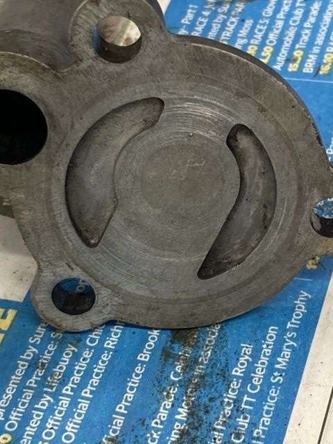
The bores themselves are pretty shiny, see below, therefore is it worth getting them glaze busted while they are in the machine shop?
Final question of the evening, is the bush that sits under the dizzy/oil pump drive, supposed to come out? The WSM appears to show it as removable.
Karl
-
Dave, it always seems so simple when you read the manual!
The scuff is pretty minor, but there are also a couple of areas of corrosion where the water flows between the head and the block, so I think it's probably worth getting the head decked to address these and the scuff, after all, I don't plan on doing this again anytime soon.
The local TSSC hive mind have put me onto a couple of local machine shops, so I'll give them a bell this week to get an idea of cost.
After yesterday's major disassembly exercise, I started with something a little lighter, flatting back the sump and timing gear cover for a fresh top coat of enamel black.
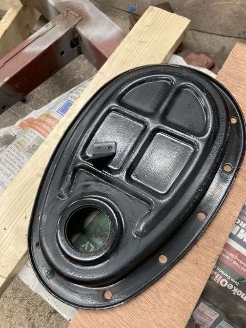
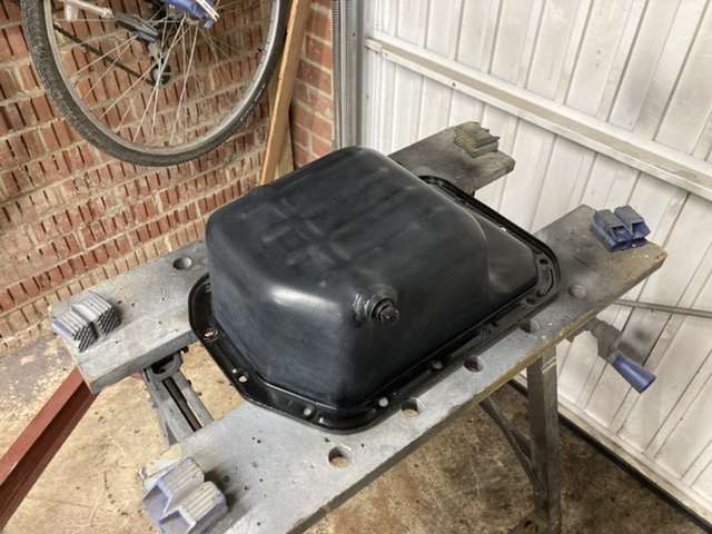
I used a piece of Scotchbrite for flatting back the bulk of it, with some 100 grit for a couple of the runs that I'd managed top put on the engine back plate.
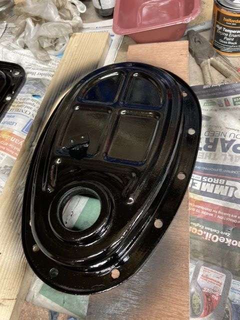
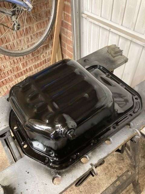
They may just be engine components that most people will never see, especially the sump, but it's nice to have them clean in glossy black.
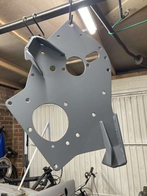
The back and front plates also got the same treatment, but these will need a bit more work as I managed to put a number of sags and runs into the finish.
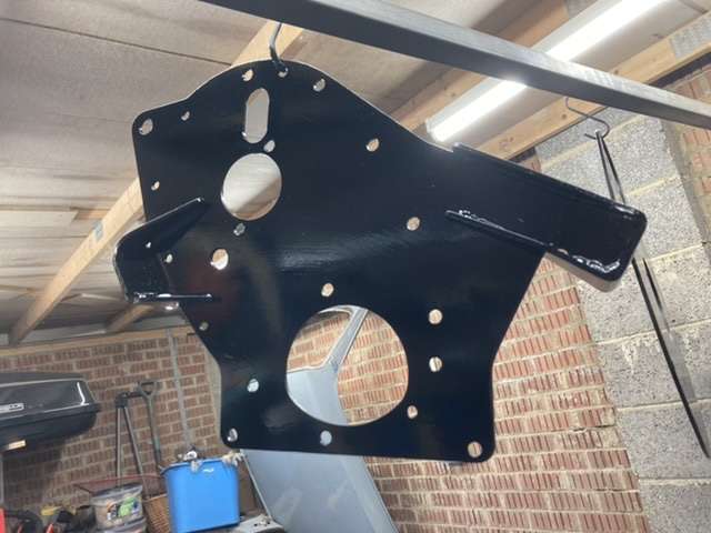
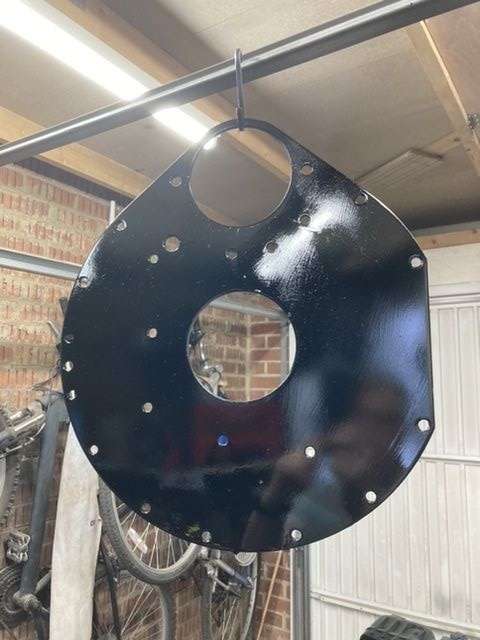
The front plate is actually pretty OK, its the back plate that will need flatting back, as I had the pressure too high when spraying, so entirely my own fault.
The rest of the painting went fine, giving some items to add to the 'clean' table ready for when the engine goes back together.
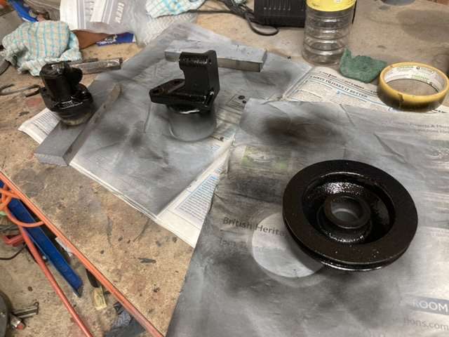
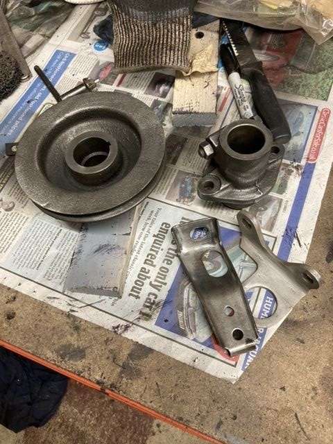
That's the front pully, alternator mount and dizzy pedestal ready to go.
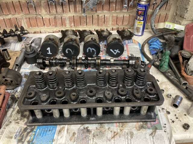
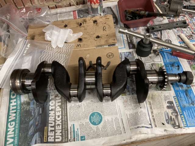
Aside from the painting, I did actually manage to get something vaguely technical done, checking the condition of the camshaft.
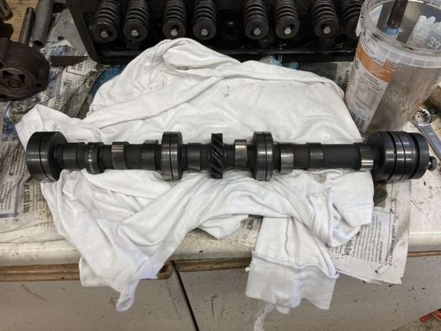
Here it is pre-clean up.
Slight panic attack when comparing dimensions with the WSM, as mine appeared to be massively out, but then dawned on me that the WSM is for an early engine, which mine is not, so over to the Haynes manual instead.
I'm rather assuming that the later 13/60 engines used the same camshaft, as mine is spot on the book spec for one of these.
As for the cam lobes, these were all immaculate, with no sign of wear.
The above was taken pre-clean up, so the marks are merely dirt, rather than damage.
So, following a thorough clean up, the camshaft joins the sump and timing cover on the 'clean' table.
Next up disassembling the head.
Karl
-
1
-
-
Thanks for the suggestions, I will have to try the cable and drill trick first, and when the car is back up and running, sometime in the next 15 years, I'll give the soda crystals a go.
I didn't manage to do anything yesterday as I was out test driving our next car....

.....I say car, it's actually classed as quadricycle, but it is an EV, and ideal for most of the driving that I seem to do these days
Today though I made up for my 'cheating' on the Triumph and returned to the challenge of getting the head off the block.
A week of soaking the head studs in penetrating fluid had made not an iota of difference, and the head was showing no signs of wanting to move, so onto plan B.
Plan B involved welding a head nut onto each of the studs, trying to get as much heat as possible into the stud in order to try and break the seal created by 50+ years of corrosion.
In all but one instance, this approach worked, though often needed multiple heating cycles before the offending stud would move, but even then, only with the assistance of a 3ft breaker bar.
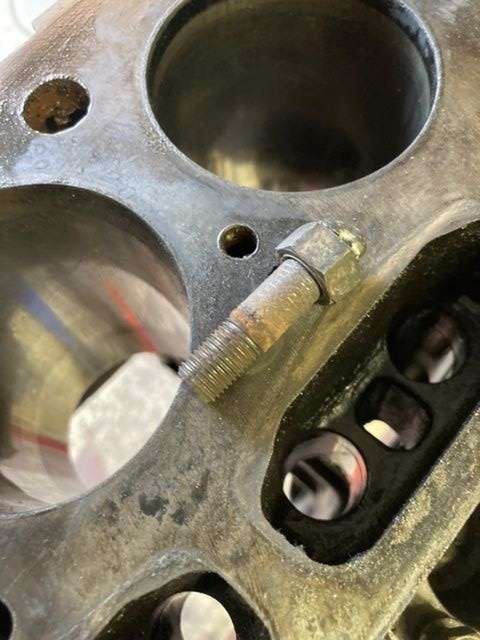
The one that didn't wind out, snapped!
However, given that it was the last stud left in, and there are no dowels between the block and the head, I was able to start gently twisting the head, applying more penetrating fluid as I went.

About 10 minutes of this first got the head able to be fully rotated around the errant stud, and then, slowly but surely able to be lifted off the stud, leaving me with this.
I started with the same approach as before, welding a nut to the top of the stud, but the distance between the top of the stud and the block was such that the real heat just wasn't getting to the base of the stud in the block.
With that not working, I cut off the stud about an inch above the top of the block, and then used a tap & die set to cut a new thread, allowing me to attach a nut much lower down, where the heat of the weld may actually have an impact.
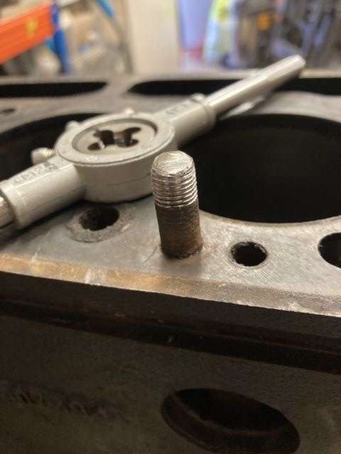
Again the breaker bar came into play, and made short work of the remains of the stud, which was soon out.
Unfortunately in the process of doing all this I managed to scuff the top edge of No.1 cylinder with a flap disc, so this will need to be addressed.
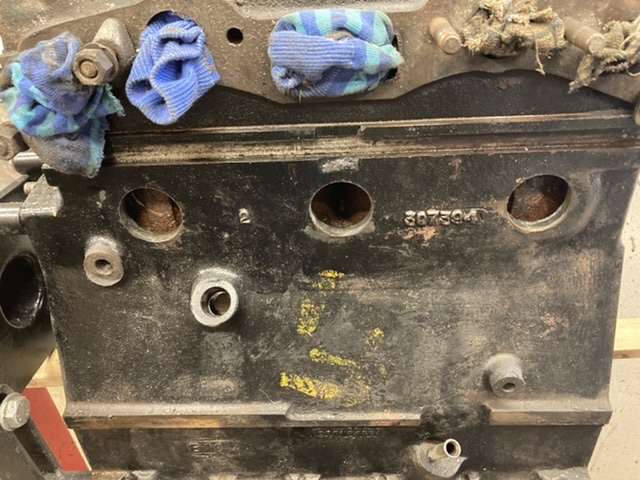
I was planning on getting the head checked for flatness, and getting it skimmed, so I will do the same with the block itself, particularly given the corrosion around some of the water passages in the top of the block.
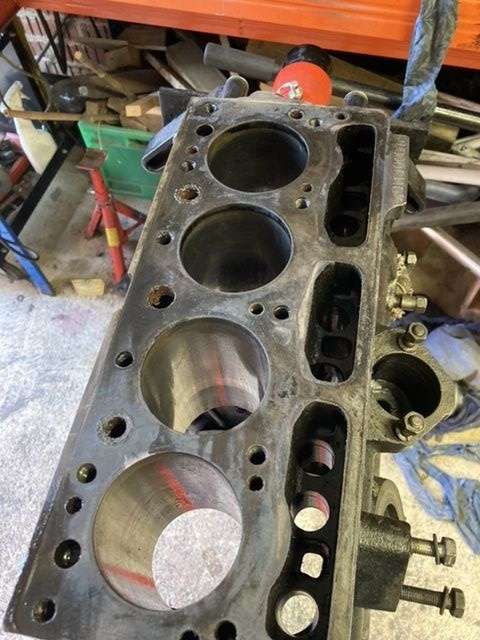
As you can see the bores are in really nice condition, with no ridge at the top, just a line of old claggy oil and carbon deposits that I will need to clean off.
With the block stripped practically bare, I liberally brushed on some Gunk, and fired up the steam cleaner, letting everything soak for 15 minutes, before blasting the muck off.
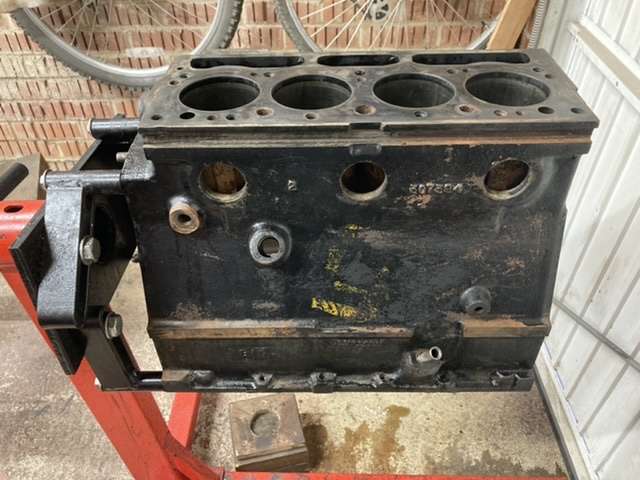
It's quite entertaining putting the nozzle of the steam cleaner up against one of the oil ways, and watching crud fly out of the various other oil ways around the block. This was repeated until I was just getting clean steam, and the same for the water ways.
Following that, the block was then dried off with a hot air gun, ensuring that all of the water had been evaporated off.
The pistons were dropped out of the block prior to attacking the stud, so these, along with the head and cam shaft were placed in the 'dirty' area to await clean up.
I need to buy a valve spring compressor this week, so that I can fully dissemble the head, after which everything will get a very thorough clean up, before it heads off to the machine shop.
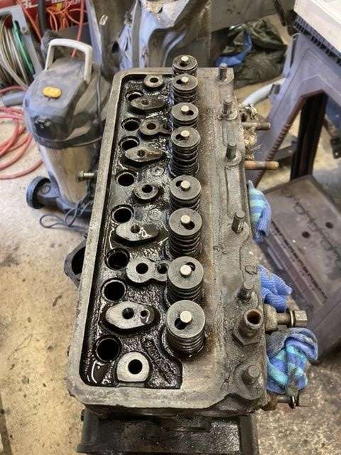
Also in the dirty zone, and awaiting both a clean up and checking, are all the other head components.
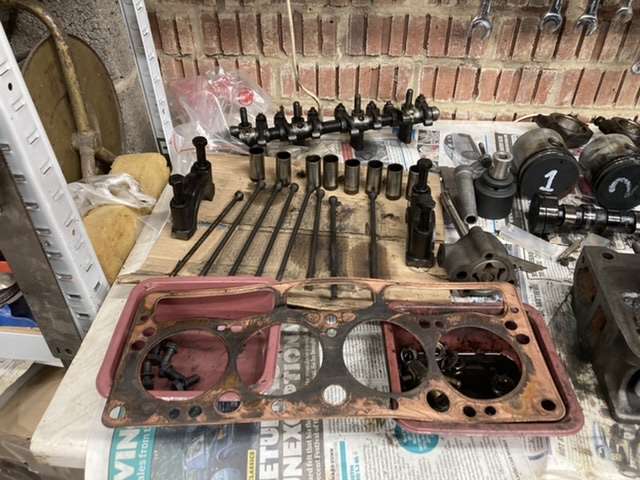
Don't worry, everything has been stored in order, so that it will go back in the same place as it came from when everything get's rebuilt.
I'm not re-using the head gasket, it's just there to confirm the correct orientation for the new one.
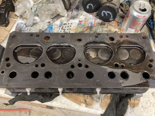
The head that it sat under appears to be in good, if somewhat mucky condition.
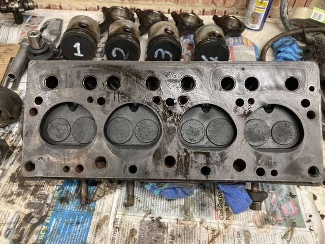
Before I take the valves out I will do quick drain test to see how well the valves are actually sealing.
Now normally that would be it for the weekend, however given the current circumstances, and the unforeseen bank holiday, I'm hoping that I might get some more clean up done tomorrow.
Karl
-
1
-
-
Colin it’s more the ones at the back of the block and head that worry me as they will be all but inaccessible one the bulkhead goes back on.
The ones on the side of the engine would be a pain, but at least you can reach them.
Pete what’s the best way of flushing out the waterways?
My parcel from Mick Dolphin turned up today so I’ll post some pics later in the week.
Who would ever have thought that receiving parts with a Leyland logo on would engender such feelings of trust!
Karl
-
Paul, that's a good point about using these nuts for the valve pedestals as well.
I'll have to add these to my order when I place it.
I've ordered a number of parts for the bottom end rebuild, but these won't appear until next week, so this weekend was instead spent on cleaning, stripping and painting.
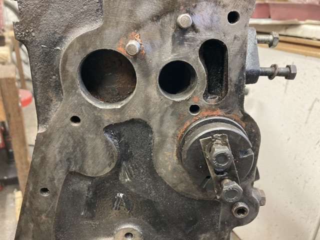
First up was the core plugs as I had noticed that at least one had already been replaced, and another was definitely the worse for wear, as a scrub with a wire brush soon showed.
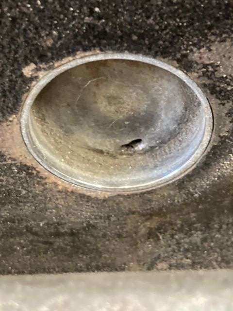
This was one of the three on the manifold side of the block, furthest right in the pic below.
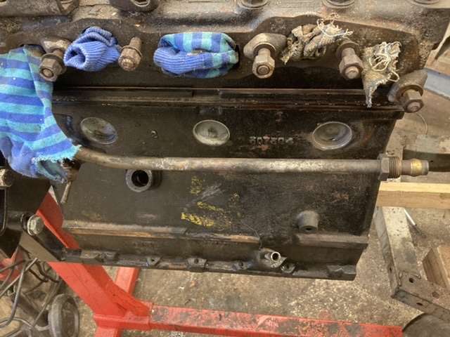
That pipe is very much in the way, so I started the head removal process slightly earlier than anticipated, as Triumph in their wisdom had decided that the bracket which secures the pipe to the head, is attached by a bracket under a head nut!
Therefore you have to release the pressure on the head gasket, just to remove this pipe.
Great piece of design there Triumph!
Given that the core plugs were an unknown quantity, and having heard horror stories of core plugs failing in inaccessible locations after engines had been re-installed, I have decided to go the whole hog, and replace practically all of the core plugs. The only exception is the plug covering the rear cam shaft bearing which has obviously been replaced at some point in the recent past.
So there followed an hour or so of ripping out the old core plugs, using a half inch masonry chisel and a lump hammer.
I found that striking the plug at it's base with the chisel caused it to pivot out, making it fairly straightforward to remove, in most cases.
Excuse my old socks!
These 3 were about the most difficult, and I ended up breaking one of my screwdrivers in the process.
Note that I have finally been able to remove the dizzy pedestal! It was stuck on with a ton of gasket sealant, but more later.
Still a bit of gasket sealant to be removed there, so something to do during the week.
The plug below is pretty representative of all of the plugs which came out of the block.
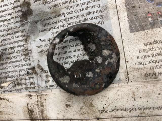
I will hold off fitting the core plugs until the block has been painted, which will only happen after I have got the head off.
As I said, I wasn't expecting to take the head off, but having been egged on by the two Petes, not that it took a lot of egging, but given the need to reach core plugs, and refurb some of the brackets which sit on top of the head, it's the right thing to do.
I removed the rocker shaft and pedestals yesterday, along with the push rods, making sure to keep everything in order, and in the right place.
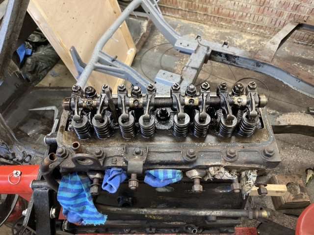
This also allowed me to access the head retaining nuts and studs which sit beneath the rocker gear.
Now, all of the nuts came off without a fight, but as we all know that doesn't mean that the head will, and sure enough mine refused to budge.
Also, Sod's law, I ran out of penetrating fluid, so I sprayed on what I had left, and left it overnight.
I tried double nutting the studs out, but that only worked for the ones inside the area covered by the cam cover itself. Unsurprisingly the ones down the edge of the block were stuck fast, so with my supplies of penetrating fluid replenished, everything has been thoroughly doused in fluid, covered with a cloth, and will be left to soak now.
I'm tempted to replace the take off for the heater from the top of the head, but that just feels like tempting fate.
We'll see how things go this week, but if needs be I'll break out the welder and weld nuts to the top of each of the studs, as I'm resigned to replacing these studs given they are likely to be corroded, and let the thermal shock of the welding loosen them up.
As components have been cleaned up and painted, they are being added to the 'Clean' table.
Which also includes a number of the new components required for the rebuild.
The engine front and back plates have been cleaned up, rust stopped, and primed ready for a coat of gloss black, along with the crankcase breather tube.
I mentioned the dizzy pedestal earlier, this had been stuck to the block as if glued on, which to be fair it sort of had been, but with a bit of levering with an old screwdriver, it finally gave up its purchase.
With it loose, I was able to add it to the clean up pile, which included, in no particular order, the lower fan belt pully, the pedestal, engine lifting bracket and throttle cable bracket.
These have all been rust stoppered, and will get a coat of primer later in the week, ahead of a coat of nice shiny black at the weekend, weather permitting.
Despite this being a bit of weird, and somewhat sad weekend, I am counting this as good progress, even if I do have a car in slightly more pieces than I did the week before. Hey ho.
Karl
-
Looks like you have plenty to keep you busy this winter Colin!
I hope you find the source of your leaks swiftly.
Karl
-
 1
1
-
-
Thanks Pete, I’ll give them a go.
Used to use Minispares years ago when I had my first car, obviously a mini.
Thanks
Karl
-
Thanks both of you for your thoughts on this, it really does help to have members of the hive mind to bounce ideas off of.
I’m not averse to popping the head and replacing the head gasket, in which case I would also strip the head and get it checked for flatness.
I would also look to replace all of the head nuts with the upgraded ones that Paddock’s sell, and which I am assuming do away with the need for a washer, given the broader footprint?
What I will do is finish rebuilding the bottom end, before I start on the top end.
Thanks
Karl
-
Had a chat with Mick Dolphin today and have scored a set of NOS big end bearings, as well as a set of NOS thrust washers.
I also spoke to Paddocks about their tri-metal bearings, turns out they are made by King, so excellent quality, so I ordered some.
Even though the oil pump checked out OK, I’m a bit suspicious of the pump given the damage to the bearings so Mick is also shipping me a NOS FAI oil pump.
I’ll check the spec’s before I fit it, but at £25 it’s worth a punt.
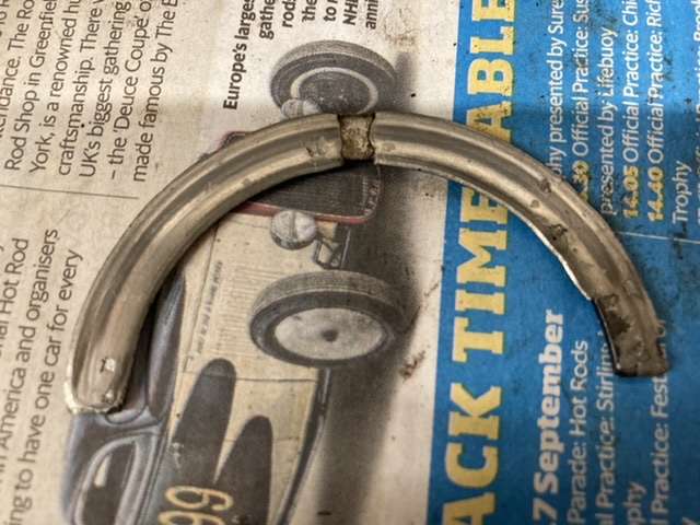
Finally, there are a couple of brackets attached to the head by the head studs, the throttle cable, and the heater bypass pipe.
If I remove these nuts, do I need to release the entire set of head nuts, or is it OK just to remove these two?
I have ordered new washers to go under the nuts, but don’t want to get further into this than I need to just to paint a couple of brackets.
Thanks
Karl
-
I didn’t cancel the digital callipers as they have been on the wanted list for a while, predominately for my model making, so an easy justification in this instance.
I did go over all the journals last night with the new callipers and everything is as per book spec., so rather than stressing it, I’ll go with a set of standard shells for mains and big ends.
I have pinged Mick Dolphin a mail as it looks like he has the big end bearings in stock, and potentially the mains as well. These are all VP NOS, so my preference against some modern bearings.
Having said that, I did read that the County tri-metal bearings are actually made by King, and very good quality.
On the thrust washers, this one checked out as marginally under spec.
Not that I will be reusing it given it’s battered state, while this one was unsurprisingly well under book thickness.
I have asked Mick if he has any, but I’m not holding my breath as there weren’t any on the list.
The only other work I’ve done on the engine this week is remove the crank case breather tube, to make painting the engine easier, that and scraping old gaskets and sealant of the front face of the block.
Not exciting, but very necessary all the same.
Thanks again for all the guidance, much appreciated.
Karl
-
Thanks everyone.
First off this evening I checked the main bearing and big end bearing journals on the crank with a calliper gauge, and they all came up at book spec, so are as manufactured.
Next up was checking the faces of the crank which face the thrust washers.
A finger was run around each face, and no trace of roughness or a lip was detected, so I’m counting that as good to go.
Finally I measured the thrush washers themselves, and as expected, they measure up as just below base WSM spec.
Therefore I am going to go with a set of standard replacement thrust washers, as anything larger won’t leave sufficient clearance.
I used a standard set of callipers, i.e. non-digital, to measure everything, but have ordered a digital pair to do a final check before I start ringing around for a decent set of tri-metal bearings.
I figure it’s worth spending £20 on a better set of callipers, to ensure that my reading of all the measurements are spot on.
Any suggestions welcome.
Karl
Thanks
Karl
-
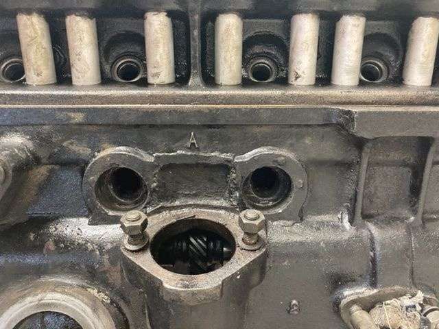
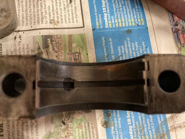
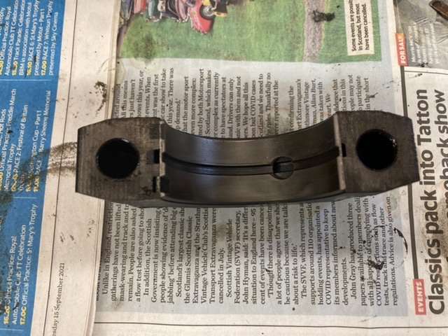
I had a look at the thrust washers just now, and it took me a while to work out where they were supposed to fit.
The WSM is less than clear on the topic, so it took me a couple of minutes to figure out that they go either side of the rear bearing bridge, where the arrows are pointing.
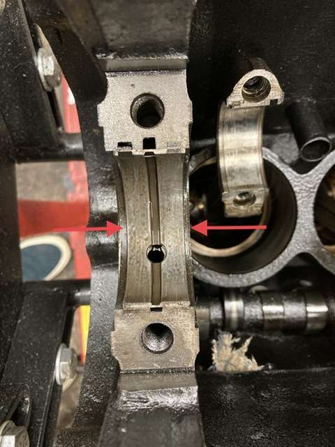
I’m assuming that is correct?
With the thrust washers in place, I put the crank back in and measured the fore and aft movement, which came out at .010 of an inch, which is within tolerance according to the WSM.
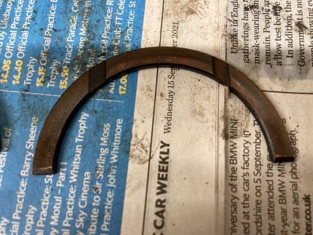
This is what the thrust washers look like.
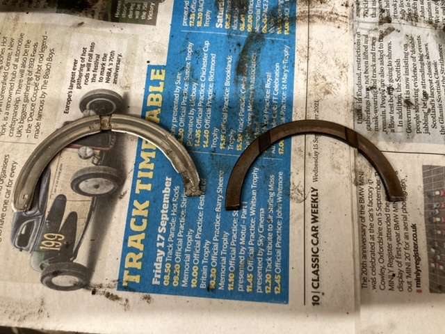
One doesn’t appear to have any white metal on it at all.
Whereas the other just looks a little tired and battered.
So, given the above, I am assuming that I am in the market for a set of standard thrush washers.
I also checked the bearing shells, for evidence that they were over size, but aside from some part numbers and a VP logo, no indication of them being +10 etc..
So again, I am assuming that these are standard size.
Karl
-
Johny, the bores are as smooth as silk I’m glad to say, with no evidence of scoring, so it looks like I will get away with a bottom end rebuild only.
I haven’t confirmed that the crank is standard size yet, but assuming it is, as there is no evidence of anyone having been at it since it left the factory, but something to check this evening.
There was no longitudinal movement in the crank before I took it out, but then I didn’t measure the tolerances at that point.
What I will do is pop it back in, with the thrust washers, and do a proper measurement of the end float.
With regards the bearings, tri-metal is the way I would prefer to go, particularly given the close call on the current shells, so I have some research to do this week.
Thanks
Karl
-
Johny, Pete, thanks for the guidance on this.
I finally got around to checking the tolerances on the oil pump, and they are all comfortably within the tolerances stated in the WSM, and are pretty much on the upper, tighter end of the scale, so it looks to be all good.
That's the good news!
I also managed to crack the end caps off the big ends, and this revealed a similar story to what we saw with the mains before.
That's quite a lot of copper showing on cylinders 2 & 3.
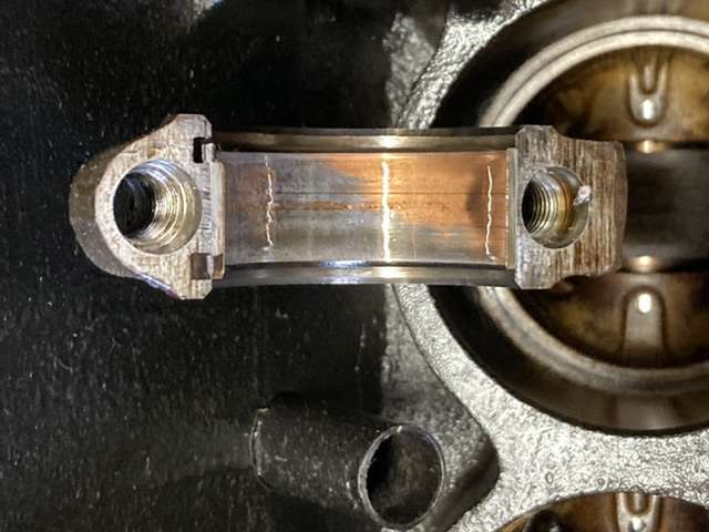
It certainly doesn't improve in close up.
So, as well as a set of main baring shells, I am also in the market for a set of big end baring shells as well.
The crank itself looks to be perfectly fine, with no striations discernible on the journals.

I also managed to remove the front plate, which revealed the remains of the rather quaint paper gasket.
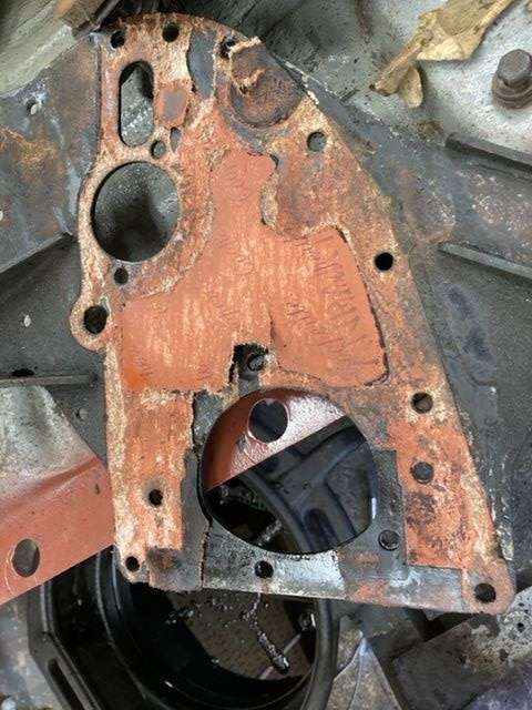
Doesn't look like it has seen the light of day since it was assembled in 1968.
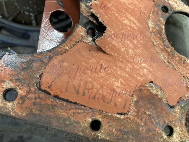
Anyone know what was so special about Cooperite?
I'll tell you one thing, it's magical power was certainly not coming off the front plate!
I had to resort to the razor blade and then finally a strip disc, as the gasket sealant was just not budging otherwise.
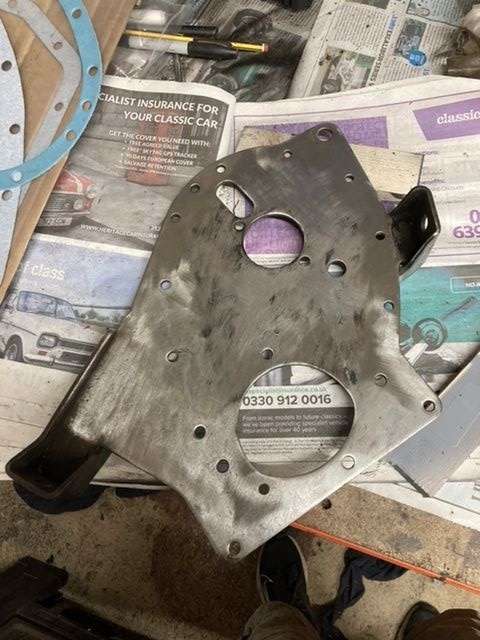
I still need to clean up the engine mounting lugs, but I will probably use the blast cabinet for that.
However here it is with the freshly cleaned and painted timing cover checking the fit of the gaskets.
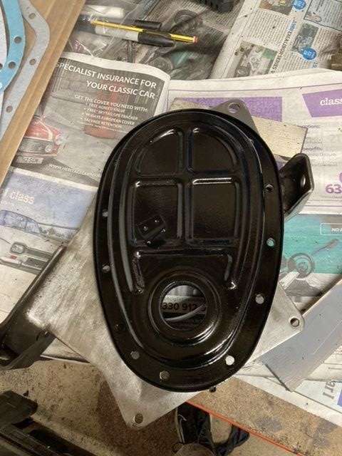
The cover needs a rub down, and a final coat of gloss black enamel, after which I will tuck it away somewhere safe until needed.
Which leaves me with a question of whether I need to pull the pistons and check the little end bearings?
Again, all suggestions willingly received.
Karl
-
So, following the wisdom of the hive mind, I spent this afternoon removing and stripping down the oil pump, which left me with the following:
This is the top of the pump, note circular scratching, particularly visible at the top of the photo.
The impeller itself wasn't scratched, but was covered in little pits, see below.
Not sure if these are rust, if so unclear how, as when removed the pump was still full of oil.
The section that the impeller sits, stator?, also exhibits the same pitting:
The interior of the pump body looked OK, but is now sitting marinading in Gunk to remove the external muck.
I haven't checked any tolerances yet, as I can't find my feeler gauges, but is the oil pump toast as is?
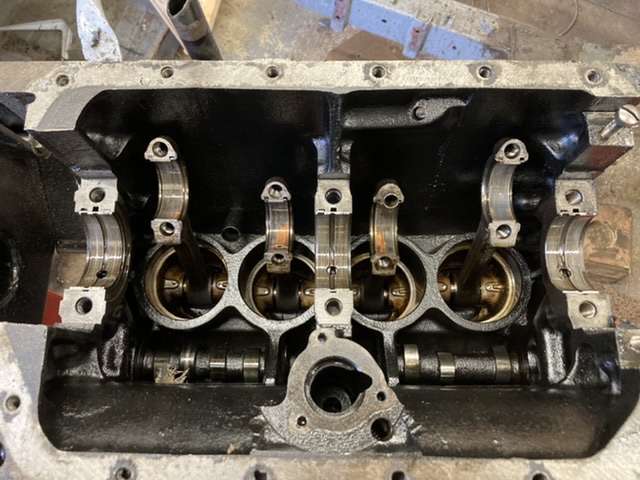
Again, given the guidance provided by the forum, I cracked the main bearing caps, which unearthed the following:
This is the rear bearing, note copper/brass showing through in the top right.
The centre bearing was even worse!
Showing considerable wear, while the front bearing....
....exhibited none at all.
I'm guessing that the centre bearing is under the greatest load, followed by the rear due to the flywheel, while there is relatively little acting on the front by contrast.
I did rotate the crankshaft, and run a nail over each of the journals, but all are scratch free, with no discernible wear.
Given all that, I am assuming that I am in the market to get the crank journals checked by a machine shop, and a fresh set of bearings ordered?
Karl
-
I’ve got a WSM and a set of feeler gauges so will check the oil pump for conformance.
As for the bearings, I’d rather leave as is, but will rotate them by hand to see if there are any rough spots, but if the oil pump shows any signs of scoring then they will have to be looked at.
Thanks
Karl
-
Johny, given that the oil pump is just sitting there, it seems churlish not take it out and check the tolerances.
I’ll clear the bench tomorrow and take a look at it.
Karl


** 26/02/23 Heading Up ** Probably how not to restore a Herald!
in My Triumph Restoration Project
Posted
Thanks Pete, I might see if the machine shop can sort those out while they are checking the head, and decking the block.
Karl