

Bfg
-
Posts
1,168 -
Joined
-
Last visited
-
Days Won
44
Content Type
Profiles
Forums
Blogs
Gallery
Downloads
Store
Events
Posts posted by Bfg
-
-
53 minutes ago, Mathew said:
One day it will be sorted, and then what will you do! Looking good, i suspect you may return the centre H to firm up the dash and scuttle shake. Does look like alot of water in the oil. But you will get a lot under polythene . Fresh oil and a run out is my prescription. Check the water and oil levels to see if one is migrating to the other. Have you forgot the carb overflow problem or has that been sorted?
One day ..I'll be too old to drive the flipping thing ! ..just kidding (..sort of )
We drove the car before without the H-frame ..with no issues. But yes, we'll see now that the tunnel cover is in and four more body-to-chassis mounts have been added, so the car's body shell now ought to be taut ..which might just add to highlight the windscreen / scuttle shake. Oh yes., yesterday I did up two loose bolts holding the fuel tank in. One was loose enough for its penny washer to have been an annoying rattle, while the other had a stripped thread. NB, the steel petrol tanks in these cars do add considerably to the stiffness of the rear deck and B-posts ..but only when bolted up tight.
Immediate plan is to re-torque the head, and drop the sump to clean that out, and of course to change the oil and filter. I'll use a slightly cheaper oil for flushing, and at the same time see what's what after the car has been started and run for a while.
You're very right though.. "Fresh oil and a run out is my prescription" reminds me that the issue need not stop my world spinning on its axis today, as even if those figure-of-eight-gaskets are seeping water passed - then they can just wait a while (with the car on the road) before its done.!
Hey, no incredibly I've not forgotten that one.. another job done with new (supposedly matched pair) shut-off valve seat and needles ..for both carbs. .

cheers,
Pete
-
Wiring task is mostly done . . .
I'm very pleased to say that my immediate work on the wiring is now all but done (..just a few wires to the wiper-motor need sleeving and securing) but everything electric (presently tried) works as it should.
 The LED side lights and indicators (..particularly noticeable at the rear) are much brighter, and now thanks to TR3-Bob (of the TR forum) I even have hazard warning lights.
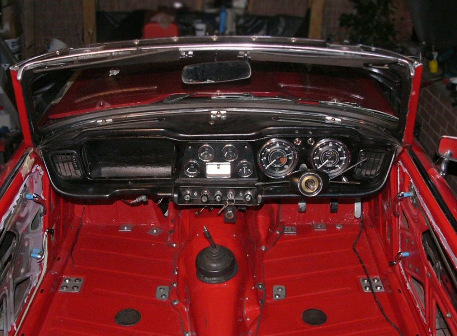
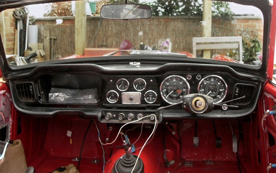
Having removed the timber, and still hoping to do without needing the dashboard supporting H-frame, I've also revised the dashboard layout, switch arrangements and cable runs, so the speedo is now outboard of the rev counter (the rev counter and speedo have swapped places). The minor instruments are in their same position, save of course being mounted onto the steel facia panel from a TR4 (they were previously mounted into the TR4A's wooden dashboard). A TR4 three-position light switch is on the dashboard to the right of the steering (the light switch used to be the LH column switch). The column switch immediately besides that (also on the RHS)(this used to be the overdrive switch) is now the main / dip beam switch (which used to be foot operated switch next to the clutch pedal). The indicators switch is there too near the steering wheel (when it's refitted). The overdrive switch is now to the left of the steering column ie adjacent to the gear change (this switch used to be for the lights).
The rheostat for the instrument lamps is yet to be mounted but that will be under the dashboard behind the central switch plinth, together with the fan blower switch, which is presently crudely mounted on a bracket projecting from the heater itself.
Left to right on the central switch plinth are now ; wipers, screen-wash, heat distribution (face / footwells), then the ignition switch, and finally the choke. The hazard warning light switch is tucked under the RHS of the dashboard and in the bracket that used to be for the bonnet release. That release cable is now on a separate bracket just under the RHS face vent, which is much very easier to reach.
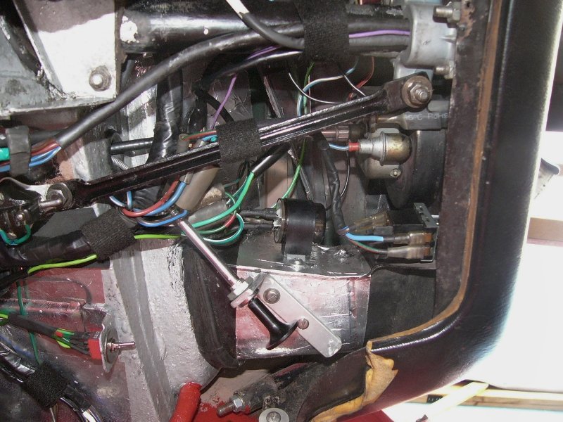
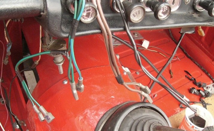
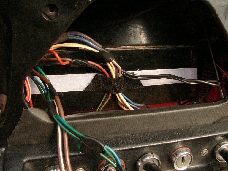
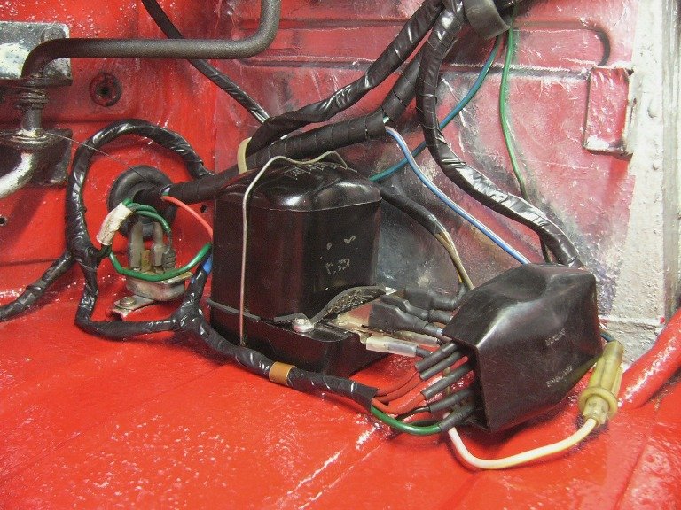
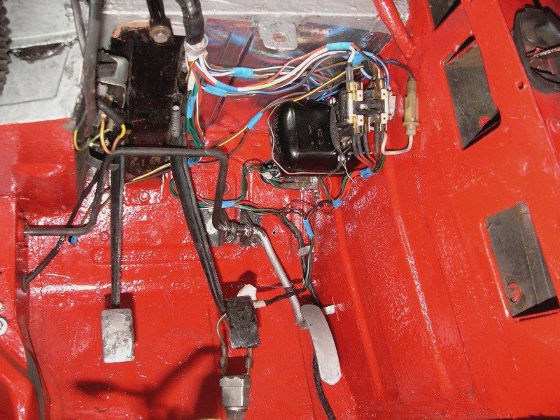
^ bottom centre is the bonnet release, which looks odd at such an angle, but in fact is as easy to pull when standing outside the car as it is from inside. The angled cable is very much more direct and a smoother run than it was originally, so the bonnet pull feels lighter. Similarly swapping the rev. counter and speedo made each of their cables run smoother. The bonnet release bracket is mounted onto the bottom of the air vent trunking, and as you can see just above this is the indicator relay. The ticking relay (for LED lamps) can be better heard than the original Lucas item fitted way up in the corner of the passenger footwell.
The red switch for the hazard warning lights can be seen in the bottom-left of this photo. And the headlamp switch is on the dashboard besides the indicator relay. The pull-type brake light switch can just about be seen mid-way up the left hand side of the photo. Naturally the wire run between the fuse box just out of sight in the bottom left corner and the brake light and hazard warning switches are short & direct. Likewise between the light switch and the main/dip switch. As again are those between the indicator switch, the relay and the hazard switch. I've left the steel cover off the cables going up the steering column, and instead used velcro hook n' loop. So much easier !
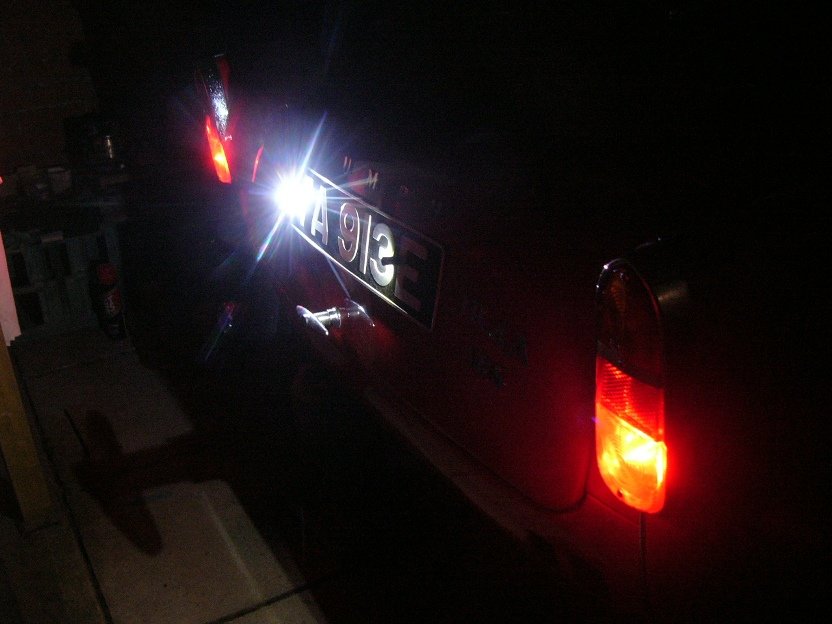
^ As I presently have no bumpers fitted, nor overriders, the rear number plate lights are fitted directly onto the plate. However I'll need to revisit those because the LED lamps are incorrectly positioned (I simply used the same holes that fastens the plate) and also show too bright a white light at the rear of the car. As you might see, the first and last letters of the registration are not illuminated. Oops !

Naturally the engine turns on the starter and the coil is wired in, the fuel gauge reads, and the (single) horn sounds penetrating. I haven't turned the engine over more than for half a second because.., the next round of disappointments were just waiting to present themselves.
I had hoped to have the car started and to have a short drive this Easter weekend (aside from one seat, the car's interior trim is unnecessary for that) but before I even attempted to start the engine. . .
^ I'd spotted this last week so as I said, I haven't turned the engine over more than for half a second ..just to check the high-torque starter-motor worked ..since I had it apart, cleaned & lubricated things, and replaced its bearing.
I had drained the water from the radiator and engine, months ago when dealing with the leaky engine block drain tap, and that is how it has remained throughout the winter. However I fear water must be in the sump.. There was no evidence of steam from the engine breather, nor white smoke from the exhaust, but you may recall when I first bought the car (..a year ago in March) I had issues with rusty water spouting from the radiator cap and expansion bottle. Re-torquing the cylinder head, fitting a seal on the radiator cap, and extending the pipe into the expansion bottle appeared to have sorted that out, as the frothing had stopped and there were no signs of emulsified oil under the rocker cover (when I later swapped out the rocker shaft) ..but now I wonder about the figure-of-eight-gaskets again. I really didn't need this issue right now, and so it's quite upsetting.
I really need to stop working on this car NOW ..so that i might get on with other jobs which left undone are costing me huge amounts of money each month (ie., a boat that I haven't touched for three years, first because of covid and then I had to move home, and then because of this (..crude expletive ! ) car).
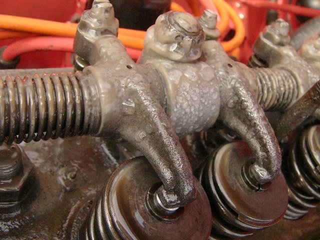
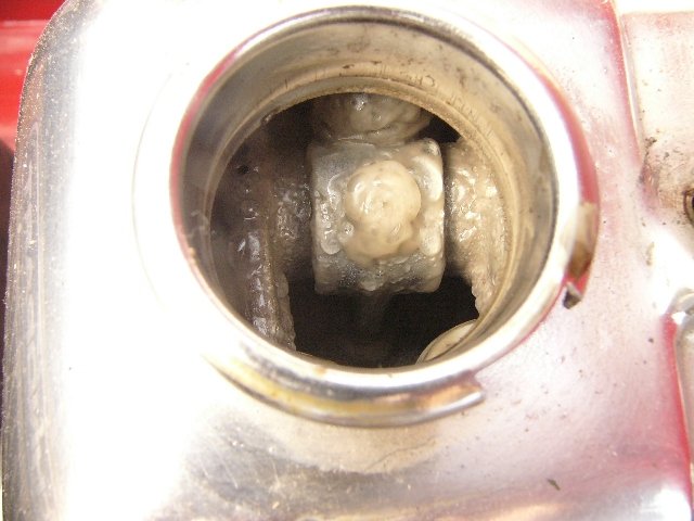
^ I hadn't ever experienced this sort of thing before, and hoped that it might just be condensation from sitting in a poly-tunnel for the past six months. I've cleaned it all off now with tissue, but in my mind there too much water to suggest it had all come in through the open breather (the rubber pipe has been off for a month or so).
After seeing this, I recalled a tell-tale sign ..which I didn't pick up on at the time. ie., when I last used the car (and was somewhat preoccupied with getting the car's suspension, brakes and steering to feel safer) ..and that was the engine's oil pressure was getting progressively getting worse. I mentioned to friends in the club that I wanted to drop the sump before I drove the car much further, to check the cranks end-float, and main bearings, and to rebuild the oil pump. At the same time I wanted to lift off the timing chain cover to check it's condition (which is why I had drained the radiator - ready to remove it). As I say, at the time there was nothing obvious under the rocker's filler cap, nor the dip stick, to suggest what I'm seeing now.
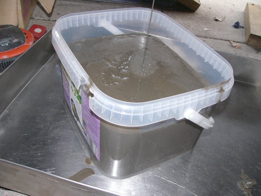
^ Oil flowing like muddy water, and even frothing ! so., certainly well mixed, despite having not turned the engine over more than a turn or two over the past six months. Naturally, if this has been in the engine and is the cause of the low oil pressure, then I hate to think what it's done to the engines bearings.

On a positive note, it is encouraging to see how tough these engines must be ..to have survived running on this. And perhaps with this issue resolved - the oil pressure ought to be much better again
")
It certainly is a new one on me.. How to ensure the engine runs cool.. simple just half fill the sump with cold water !
.. Happy Easter
-
 1
1
-
-
On 08/04/2022 at 21:13, Colin Lindsay said:
I also connected the brake light switch and the overdrive wiring, although while that is connected to the column switch, a power source has yet to be confirmed. Possibly the spare terminal on the ignition switch? It's just a simple circuit of power to column switch to interrupter switch to solenoid to earth so not too difficult.
Just a little point but, on my TR, there are two 'spare' terminals that may be convenient. The power to the overdrive relay on my car was plugged into one. However.., I note those terminals are live and unfused, and also live when the ignition is off when the key is turned back. Those are useful for things like the radio, cigarette lighter, etc., which can then be used when parked, ie., without the coil (and all other circuits) being energised.
As I didn't want the O/D relay to be live when parked, I've now taken its power from the fuse box (..which in practice / for convenience, meant a connection onto the heater fan's switch) so it ..the solenoid relay, is now both fused and only powered when the ignition is switched to drive mode.
Pete.
-
Related to the above, but more as a deterrent when out and parked.. does anyone here have experience, for or against, of one of those half-car-covers which cover the roof and windows of a soft-top ? some seem pretty expensive for what they are and yet their hooking onto wheel arches or closing a boot lid on them seems pretty crude.
Locking an open top car, or any old Triumph, is bit of a lost cause, save it still being required by insurance companies. An isolator switch on the battery is useful when working on the car, but I'd really prefer it within the car, so that in the event of a fire the electrics could at least be switched off. I was thinking about this just yesterday and realised that now I've moved the control box to under the dashboard, then there's just one power lead to it from the battery lead (formerly on the solenoid connection) and so it would be dead easy to fit a hidden-in-full-view switch to that. The toggle switch I have under the dashboard (is where the bonnet cable release was) so mostly looks like 'a hidden switch' but when switched - it turns the hazard warning lights on. Those flashing lights would confuse a would-be opportunist thief for a few seconds.
I had a steering lock on a Vauxhall FB ..many years ago, and attended an evening music festival where the parking was in a field. At the end of the evening, with the darkness inside the car, I drove off and before I knew it I had driven & turned into the back of a mini. Not one of my finest moments !
Pete
-
rowlocks ! ..I and the Chrysler are running on empty. Hopefully tomorrow the garages will all be fully replenished and selling at half price because they each have too much !
-
inbetween bouts of every kind of weather, I'm still been pottering around with 'revitalising' wiring connections ..and of course a few changes. Here's a quick gallery in no particular order of, just some of, the many things that each of us have or will face sooner or later, and which altogether take a time to clean up and make right again . . .
^ Just one of the daisy-chain instrument illumination lamps. ^^ second photo ; the temperature sender wire (where the crimping was perhaps just a little too cutting, and (white) the fraying loose (..poorly supported) feed wire to the coil.
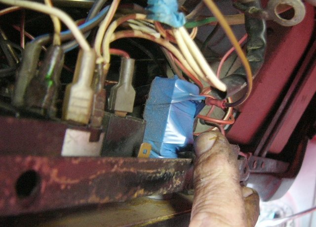
^ under the switch plinth, top the left is copper-green slime in connections onto the ignition switch, and a block of blue masking tape, which turned out to be a taped-on push button switch for an electric screen-wash pump. Access behind the central instruments and switch is insufficient for my size of hand ..Oh how I was once spoiled with an old Jaguar's hinge-open centre-console, with its fuse panel behind.. all in clear view and easily reached from the comfort of the fragrant Connolly leather seats.
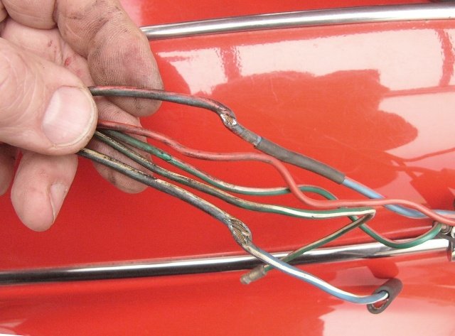
^^ right ; RHS headlamp main-beam and dip-beam wires with sheared-through insulation. This is odd insomuch as these wires connect near the centre of the car and so I cannot see how such damage occurred (nor know not when). Had they been switched live at that time then the spark would have been impressive !
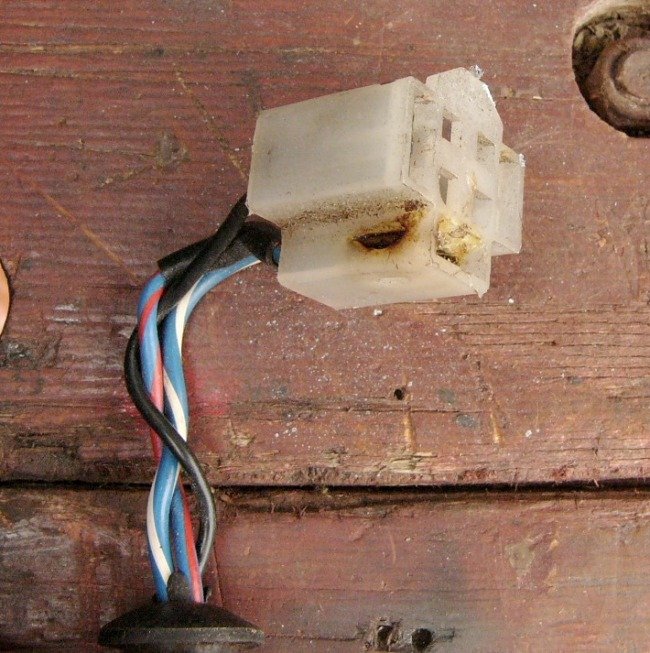
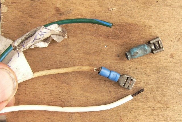
^ LHS headlamp bulb connector, melted. That particular (dip beam) wire had also been spliced immediately adjacent to the connector, and although soldered, it hadn't been protected from the elements and so had corroded through the wire again (..it literally broke off in my fingers). I replaced the whole length of wire as its shorting-out had made its insulation go hard (and brittle).
^^ right ; 25A, 7ohm resistor connected to either front indicator, where LED bulbs had been fitted. The ceramic casing of the resistor is like a hard edge and surprisingly heavy little brick, just left to hang from the wire. Changing the flasher relay made these redundant, but the lamp's wires had been damaged with these connectors ..so again had to be replaced.
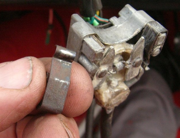
^ the shortness of these clamps, for the instruments, was discovered when I removed the timber from my (TR4A) dashboard, to go naked ! (..painted metal dashboard). Of course, because the steel dash is so much thinner - these clamps need to be 6 - 10mm longer. For expediency, I resorted to welding metal plates on, to extend their length. Nay-a-mind, only the mice will see them.!
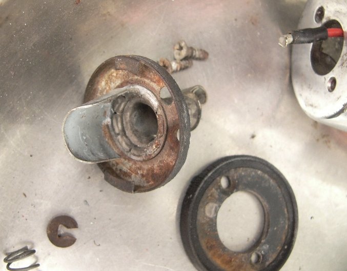
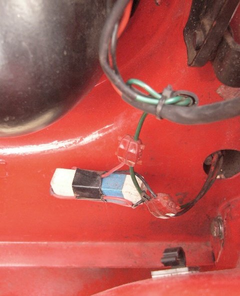
^ LED side-lamps and indicators have now been fitted in each corner ..although I have yet to remove the rear lamp units themselves, to check and clean those bulb holders. As you can see I've added a little sticky-back aluminium tape, as a reflector, behind these side repeater indicator bulb. The tape is a left-over from when I fitted aluminium-faced insulation panels inside my storage-container. I don't know what was original for these lamps, but it seemed daft to have black rubber behind a bulb. Naturally care should be taken., because aluminium is a conductor, and so this 'reflector' should be well clear of the bulb's contacts.
^^ The whole of LHS side-repeater lamp assembly has been loose on the front wing, since before I bought the car, and now I've replaced its fastening studs for new, so that it could be tightened. The front side lamp was working but obviously compromised by moisture ingress, from where the rubber seals have perished. I've cleaned up the metal work and all the connections. New rubber for these, the rear lights and also those for the headlamps ..are on order.
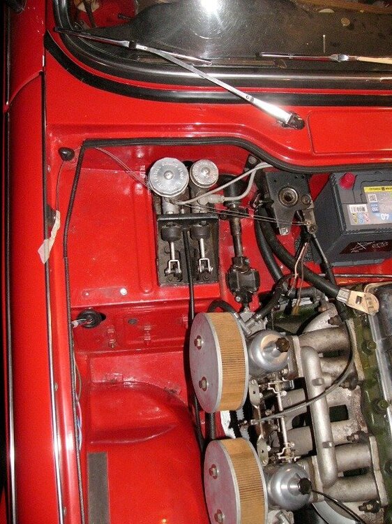
^ under the bonnet ; I've now run the front lighting-loom along and over the top of the driver's side inner-wing (rather than those wires being under the carburettors). The wires wrapping (..twice wrapped for whatever reason) has been removed and the wires are now inside a sleeve (together with a mouse in case i want to pull another wire forward). With the TR6 plastic fan, this engine tends to run cool, and so I see little need to have ducting in front of the radiator. NB. I can always add it at a later date should I find it necessary during the summer. In the meantime, without that ducting, there's a plenty of cool under-bonnet air flow, to all the other parts (..not least the car's battery, hydraulics, engine ancillaries, etc) and to feed the carburettors.
For tidiness and ease of support, I've routed the wires to the LHS headlamp, sidelight, indicator and horn, through the front valance. A pair of 30mm diameter holes were already there, so I just needed to add grommets to protect the loom from chafing.
I've removed the car's two (twin-tone) horns from the front suspension towers (..as their wiring connections annoyingly snagged my sleeve each time I reached passed them to work on the engine's fan, radiator hoses or dynamo), and now only the high-tone one is fitted. Ideally it would have been fitted low down on the RHS (to save the length of wire run) ..but the radiator's expansion bottle was in the way, so instead it's fitted near the bottom of the LHS inner wheel-arch (..which seems to amplify the hoot !). Again I found a suitable mounting hole already there. You can just about see the wire leading to that horn in the above photo. And.. with just one horn, I'm happy to be rid of the horn's relay and its additional wiring as well.
Talking with a boat-owner friend about this car's wiring, I was bewildered as to why the TR4A suddenly needed a horn relay ..when one wasn't deemed necessary on earlier cars.? Initially his thinking was that it must surely be related to Triumph going from positive to negative earth (which appears to have happened around about the same time) and the horn's wiring always being live (un-switched). I wasn't convinced. Looking further into this, I noted Roger_H's suggestion that the coil of wire in the horn button's plunger was necessarily small and couldn't take the electrical load, and so was unreliable. Tbh, that didn't make a whole of sense to me when I read the specification of the earlier car's horns drew more current.
After some deliberation (..with Katie ! ) I deduced - the introduction of the relay most likely coincided with different horns being fitted to the later cars. Let me share my route to this conclusion ...
Similarly., the headlamps have large diameter wires around the engine bay ..but still only 'normal' wires to their switch. And again, only normal (ie., relatively skinny) wires on the spurs between the main-loom's bullet connectors and each bulb. But despite the current draw of headlamps - still No relay was fitted. We deduced the reason for the heavier wires in the forward section of the lighting loom, was not specifically for carrying the current to their (now) 60w headlamp bulbs (ie., 5 amps @ 12v), but rather to minimise the voltage drop over their respective length of wire ..which of course would tend to result in the LHS headlamp being dimmer (..it being some 50" further along the loom than the RHS headlamp). So, to balance this (..and also account for why).. the wiring loom to the headlamps goes the centre of the car, to the bullet-connectors, and then the spur wires to the RHS headlamp unit retrace their 25" way back again to the lamp. This is so the length of wires to each headlamp (ie., the voltage drop and therefore each bulb's luminosity) is the same. There was method in their madness after all !
It is the length of wire (when too thin) that causes the voltage drop. And very likely, Lucas' new (12v) spiral type of horn was more sensitive to voltage drop than their old bulbous ones, which had been derived from their 6v counterparts. I'd bet, when fitted to the TR, the new horns proved quieter than the old ones !
 Oops !!
What could be done ! ?
Unlike the headlamps, the (earlier cars) horns were not locally earthed. Instead they shared both the same power source (on the TR4, a connection on the solenoid) and the same earth (through the horn button and steering column). I estimate, the wiring circuit (..of just the two horns) to be almost 240" long ..from the solenoid to one, then onto the other horn, and back, before going off to the horn-button earth.
And even though the horns are wired in parallel - the 120" loop of wire to & from the LH side of the car, would have figured in. So with new (voltage sensitive) horns, that (LHS) horn would be quieter still. On my own car the LHS horn happened to be the Low-tone horn which sounds duller anyway.
So, Standard-Triumph, together with Lucas, resolved the issue by fitting a relay immediately besides the nearest horn. The horn's power source was taken from the control box, also in the engine bay, and the horns joint earth was just there next to the relay. The horn circuit's loop, from power source to both horns, and to its localised earth on the body shell, now had a total length of around 156". It may still seem a lot, but that's the price of fitting a horn on to either side of the car. Importantly, with a relay - this is just two-thirds of what it was. And sufficient a reduction in voltage-drop for the new horns to be effective. Very likely, the old type of horn was soon-to-become obsolete, and even with a relay - the new horns were cheaper, smaller and lighter weight for Triumph.
I cannot say for certain, not least because I've otherwise been cleaning all the connections up and have shortcut the steering rack's earth, but I'd say my single horn is noticeably louder / more pronounced than when the two were fitted.
In a similar vain ; the wires for Katie's temperature gauge sender and coil used to come around the front of the car. They now go through the LHS bulkhead, along with the rev counter cable, and go directly to the instrument panel. The wire to the coli previously came from the fuse box, with an around about 116" wiring run. With it now coming directly from the ignition switch the wire is 47" long. I wonder if having a little extra voltage to the low-tension side of the coil will make any difference.? There's even greater length cut out of the temperature gauge wire. More importantly perhaps than voltages, is that both these wires are now much less vulnerable and better supported than as originally designed.
moving on . . .
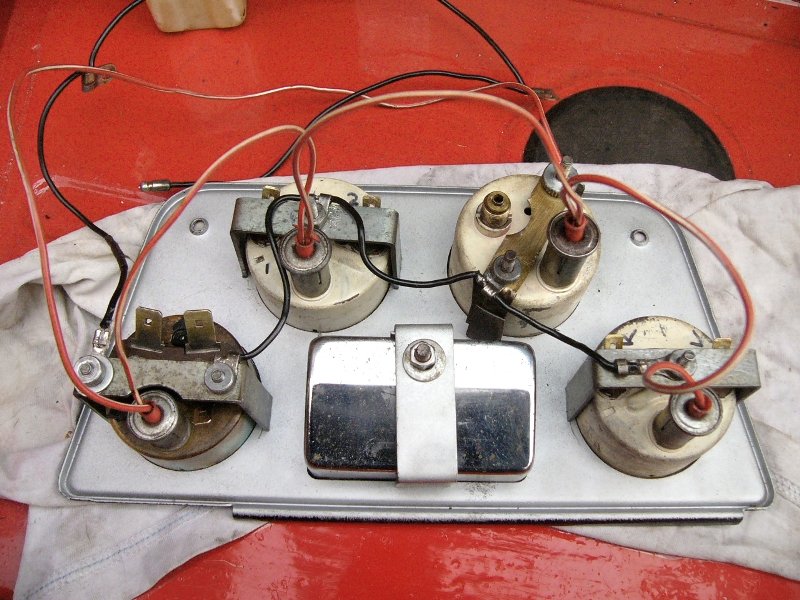
^ Back to the dashboard instruments, their electrical contacts and illumination bulb holders just needed a good cleaning and a smear of Vaseline to keep corrosion at bay. Remembering that this car was first registered in 1967, I'm really impressed with how Lucas produced such good quality OE equipment, that cost so little and yet has lasted so well, despite it having been fitted and forgotten, with little or no maintenance in all that time.
^^ right ; the centre console is very much easier to handle than the full width plank of wood (aka ; veneered dashboard). In this photo I've just refitted the daisy-chains of earths and instrument illumination lamps. Again I've gone over to LED bulbs in these.
^ with the cable wrap removed, and the cables cleaned (and of course each connector) it's easy to group the wires according to which instrument they go to. Imo, everything doesn't need to be wrapped. Personally speaking I prefer loose-fitted sleeves, wherever they are needed (ie., when they may be vulnerable to moisture, dirt or damage).
^^ second photo shows sticky-backed Velcro (white) I've stuck to the heater box, with black velcro (hook n' loop) I'm using to better secure the wires. It's a new one on me, but I thought the idea worth a try ..and first impressions are that it's easy, very flexible to position and secure.
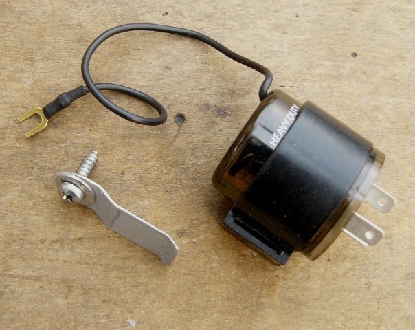
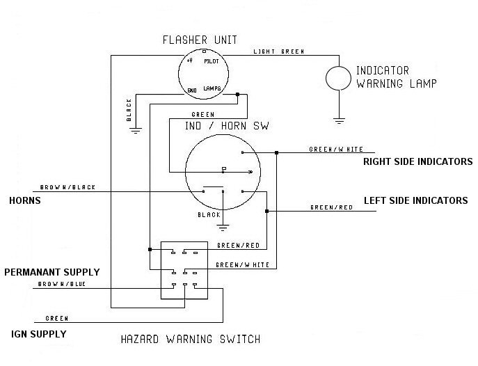
^ The LED indicator flasher unit came with a rubber sleeve but no clip for that to fit onto, so I made one (..a bit more of the back-plate of the scrapped boiler). Drilling the hole for this (.. where it was to fit on the car) was very awkward because the steering column was in the way of where I wanted to get a drill in. I'm mounting this flasher unit onto the side of the driver's side face vent's metal duct (between the air-intake-plenum and the dashboard) ..so that when it ticks - I might stand a chance of hearing it.! I have yet to fathom why Triumph fitted the original indicator relay into the far corner of the passenger foot-well, ? I kid you not.., this car's wiring loom could have been designed to work more efficiently with 10m less wire (..multiply that sort of value-engineering by 80,000 cars built and it surely adds up !)
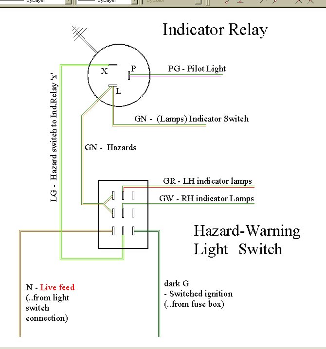
^^ wiring diagram, from Bob ..whose brilliance and kind hearted help have saved me and many others a whole bundle of working out. I've just redrawn the same here according to the switch and relay, in my own hand-writing, for my own car.
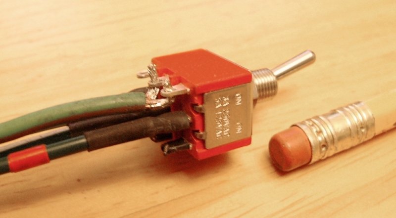
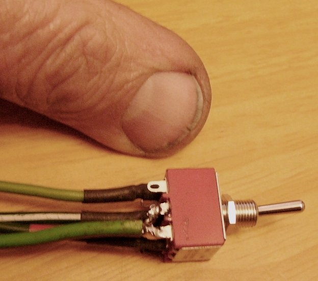
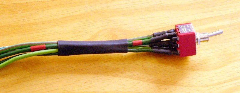
^ I like small (neat) switches and so when Bob said he'd used the smaller size, I followed suit and bought the same.. When viewing the terminal layout in the drawing above, you might want to compare that with these photos of the actual switch (with a pencil and my thumb a reference to its size (or lack of). Aside from fingers n' thumbs, my soldering iron is a tad big for this sort of work.! In the first photo you'll see the wire going to two connectors (as per Bob's instructions) so I split the number of bare wire strands into two, tinned those with solder, and then like the others bent those wires into U shapes to hook through the switch terminal's holes. Crimp those U bends tight and touch the solder to them. Heat-shrink over each and a length of heat shrink as group tie and job done. It must have been a 2-minute job (at least ! ) to connect this switch up. And I still have the other ends of the wires to cut to length and add end-connectors to. Still I'm pleased with how it came out, considering how I desperately need to go to Spec-Savers ..mind perhaps after I get new glasses I'll be less than pleased. ! ?

I haven't yet fitted it, as I'm sorting out other wires and switches first, like moving the TR4A light switch off the column, where it is easily knocked on by someone of my size getting in & out of the car. The light switch will now be a TR4 dashboard-mounted pull switch. . .
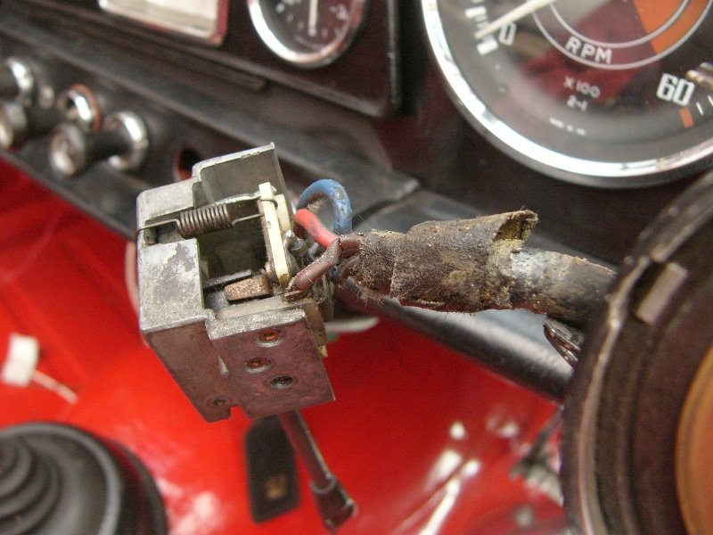
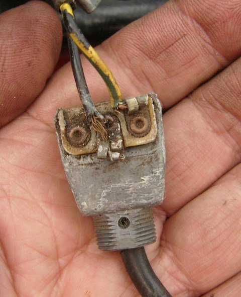
^ The TR4A column mounted light switch is now redundant, but actually wasn't in bad condition aside from some of the insulation on wires having cracked. I didn't want to disassemble the switch to clean it, and so like the other column switches used a small (water-colour painting) brush, with white spirit to clean out what I could. And then clean tissue to dry it again. I would like to use this switch for the overdrive, but it's a three position (off, side and headlamps) switch, and so I yet have to work out which connections will best work for the simply On / Off of the overdrive.
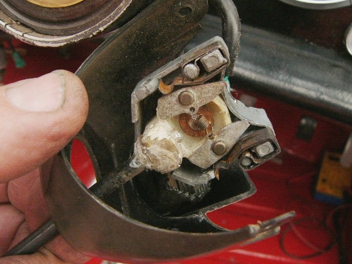
^ the indicator switch, was not in such good shape, It felt sluggish and limp handed, where the lever attached it was broken, glued back together and breaking again. It suffered with corrosion, and aside from damaged insulation on some wires, it had the wrong type of screws fastening it onto the steering column. Those should have been (I believe) small set screws, and they were coarse-threaded self-tappers. One screw had fallen out and was rolling around in the bottom of the plastic housing. It turned out the corrosion was the cause of it feeling really limp and sluggish, as the plastic mechanism dragged its way over the corroded springs (second photo). I cleaned the switch out (with white spirit) cleaned of the corrosion as n' where I could, PTFE lubricated its moving parts (carefully brushed on), and the contacts with a smear of Vaseline, and used Araldite to repair the cracked & perished plastic where the lever attaches. The wires have cleaned up fine and I've applied 'Liquid Electrical Tape' to back-up their insulation. In truth it's a temporary patchwork job that will probably only last another.. twenty or thirty years.!
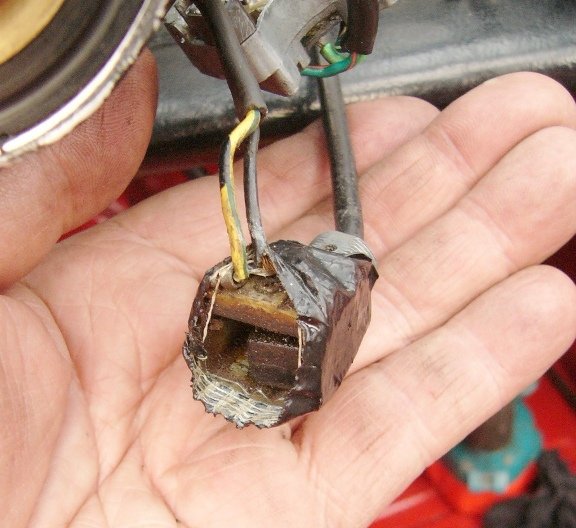
^ This is the overdrive switch, as it came off, wrapped in gaffer tape but with its end open. It still worked, but for how much longer I wonder ? I've cleaned it up inside n' out, as I plan to reuse it for the headlamp's main / dip switch. It's a two position switch but could be with three terminals. It's position on the steering column (behind the indicator switch on the RHS of the steering column) would suit me much better than the original foot switch - which I find clunky, awkward, uncertain, and generally in the way of a clutch rest for my big feet. I do like the nostalgic quaintness of a foot-operated main/dip switch, but really that's not so very important when driving the car at night. My car and I'm going to kick that foot switch out ..or use it for something else (think 007 ! ) ?
I think that's enough for today..
Bottom line though, is that each of these things take quite a bit of time to work through and correct. But after finding a host of potential unreliability issues lurking and just waiting for a wet night and an urgent appointment ..I'm glad to have taken the time to do them now.
Pete
-
1
-
-
I would have thought the hood-frame bolts need to be good n' tight, so perhaps it might be prudent to find a piece of steel tubing instead ..that will take the compression. ?
Pete
-
2 minutes ago, Peter Truman said:
Re soldering of spade or bullet connections question what do you do when you splice a new wire in I twist the two wires together and solder then shrink wrap.
I used to twist and then solder, but now I don't bother, not least because it's quicker and neater not to have done so.
But the real reason is that a splice in the wire can be 3/8 - 1/2" long and the bond between the two is already many times stronger than it will ever need to carry. Of course, the wiring on any vehicle ought to be appropriately supported throughout it's length (not least to protect against fatigue from vibration). Also wires are rarely run on their own, and so their tension between supports is shared by a number of wires. Any unsupported wires are best carried within an outer sleeve, as is originally fitted where wires are run to a isolated lamp, such as an indicator or front side light, or else pass by a hinge ..like the sub-loom to the bonnet lamps on a Spitfire, Herald or Vitesse.
Pete
-
8 minutes ago, 68vitesse said:
Not a criticism, I do what I consider is best for me with the tools available and others presumably the same.
Regards
Paul.
Likewise .. let's compare how well different techniques have lasted ..in 50 or so years ?
")
Personally I have no issues with properly crimped connectors ..that have been done with the appropriate ratchet type or hydraulic tool. However I will not have home-crimped with flat-plate wire strippers on my vehicles.
-
4 hours ago, PeteH said:
I prefer soldered connectors, But it`s never always practicable, and older cable is a sod to get clean enough to make a good join.
Likewise I prefer soldered connections. Again I use a power rotary wire brush to clean the bare wires.
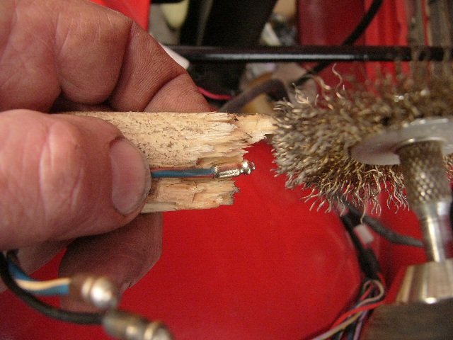
I'm not teaching you how to suck eggs Peter, but for the sake of those who are new to old-vehicle wiring, the follow illustrations might clarify the steps taken . . .

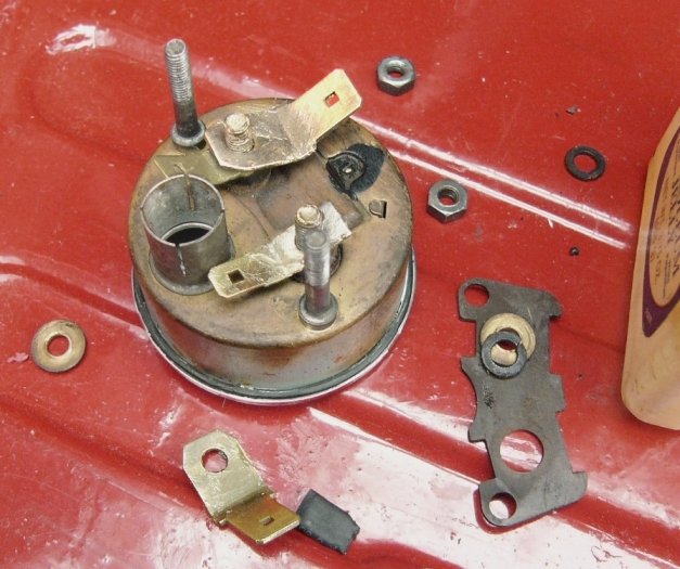
^ This was one of the wiring connections to Katie's voltage regulator, where the connector (..an incorrect big yellow-sleeved home-crimped type) was loose and very easily pulled off. Usually I would just cut the end off and strip back the insulation to reveal uncontaminated wire ..accepting that the wire's length would then be some 3/8" shorter. However for sake of illustration . . .

^ without further ado I used the wire brush on it to both comb and clean the wires ..seen here as 'work' in progress. A power wire brush is better even than Signal toothpaste for cleaning into the cavities

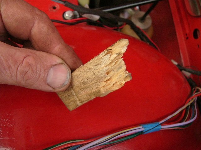
This particular wire was not as badly oxidized as many I've cleaned up using the same, very quick to do, technique. Of course rather than using a scrap of wood to support the wire as it's being cleaned, one could lay the exposed wires over a steel vice or whatever else. Still, this broken end of a batten of softwood is very portable wherever I'm working and so has served me very well as I systematically go through every connection on the car.

^ cleaned and loosely twisted to keep the wires from flaying as I solder them. The bare wire end has been cut square but the wire's insulation is as it was.

^ And tinned with solder ready for the cleaned or new spade connector. Note the solder has been taken most of the way up the bare wire but it is not necessary to go all the way into the insulation which then is damaged by the heat.
If the wire is very black from oxidation then it really ought to be replaced, as that is a sign of the wire having previously overheated due to electrical current. In such cases it may be wise to change the wire to the next thicker gauge and to fit a correctly rated fuse.! This car only had 35amp fuses, this (horn) wire ought to have rated at 5amp.
It may be that just the first few inches of the wire has really bad oxidation, in which case I find it perfectly acceptable to solder another wire in, to replace just the derogated length. I keep old looms for the purpose of donating their parts, so I often find another length of wire, with a good (factory fitted) terminal already on its end, hopefully with the right coloured insulation too. Then a simple splice with heat shrink some inches away from the wires end is an easy fix.
Pete

^ As fitted.. it's the wire going to the in-line fuse, and you can just about see its connection to the regulator now has black heat shrink, with a clear insulator cover over that and the terminal itself. Before with the home-crimped connector the LIVE terminals were exposed to being shorted out &/or corrosion and grime.
-
both bullet and spade terminals come in a range of sizes. Japanese motorcycles and Chinese clones generally use smaller diameter bullet connectors.
Conversely old British motorcycles frequently had larger types where the bare wires fed through the hole in the end and then folded back ..to be sandwiched between the bullet and the terminal. I noted today that the earth connection within the Triumph's front Lucas indicator (glass type) had this size of bullet with the wired folded back.
Of course bullet and spade connectors are used in all sorts of electrical equipment, from washing machines (where things like the front panel have spade connectors so that panel can be removed easily, to emergency lighting, and they're in a million other things too. As electrical loads &/or the space within a house gets smaller so too do the connectors.
hope that helps,
Pete
-
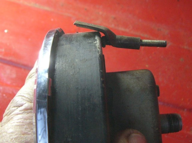
After a couple of weeks of no activity (on the car at least) here's little modification I've just done . . .
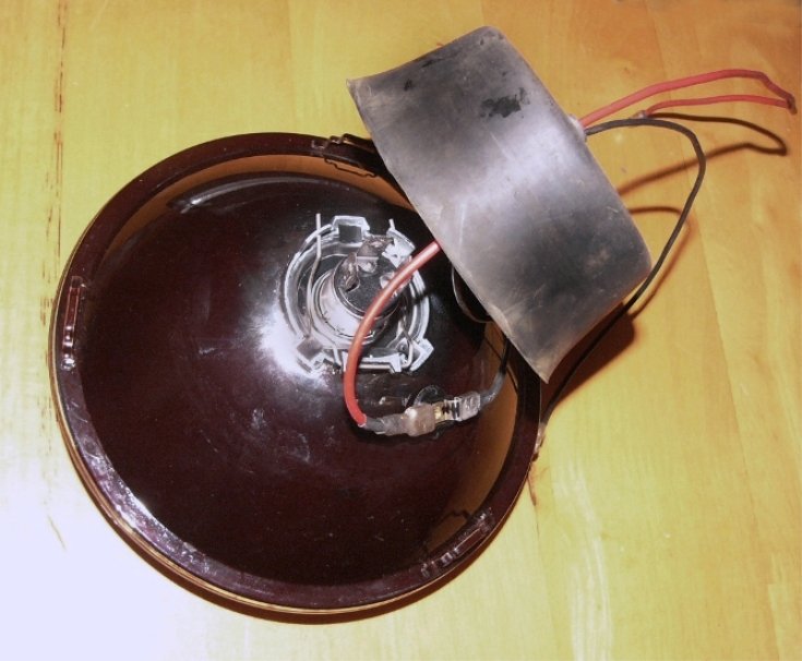
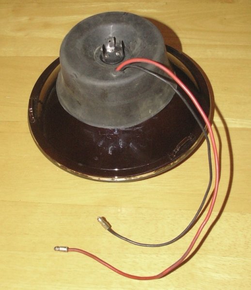
^ Adding a sidelight into the headlamp ..which was simply a matter of marking where the rubber cover goes and drilling a hole clear-inside that boundary of 12mm diameter (..having first removed the headlamp bulb of course). I have one of those stepped drill bits which steps up in 2mm increments from 4 to 20mm, so the task was easy. The two bulb holders I'd bought at the same as ordering the LED bulbs from 'Classic Car LEDs' - their part number is BA9HOP 170790, and they take standard BA9 (bayonet fitting 9mm) bulb &/or an LED's to fit. I opted for LEDs in line with my objective to minimise electrical loads / prolong battery life ..should I break down at night. I did carefully bend the terminals flat to make this easier, but as you can see, complete with wiring connections it neatly fits under that dust/water cover.
The two wires I made to suit. After drilling a 10mm hole in the bottom of the headlamp bowl and these wires being sleeved - they simply plug into the bullet terminals of the original light's wiring loom
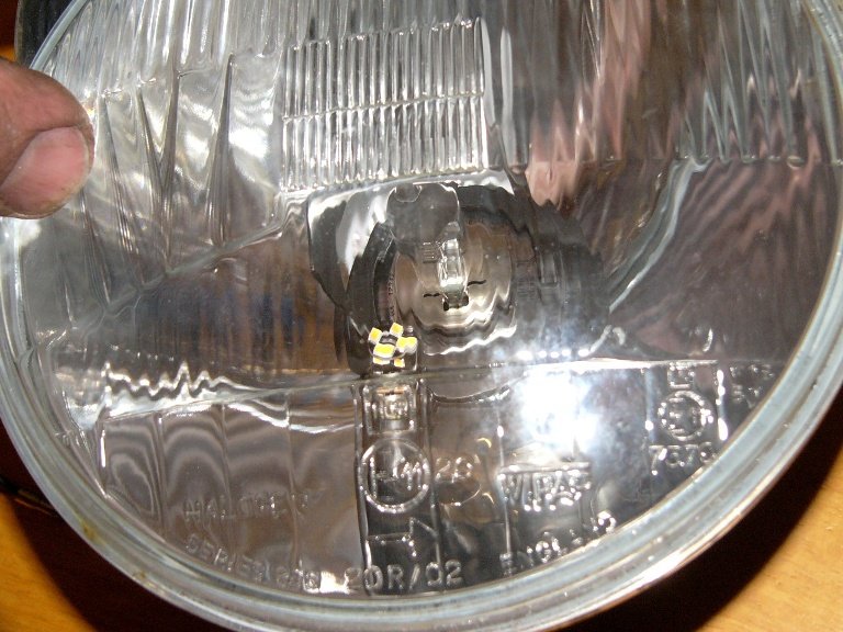
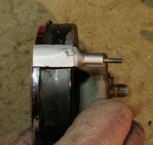
^ Katie's headlamp reflectors are Wipac, and the little LED bulb now fitted can just about be seen under the H4 halogen headlamp bulb.
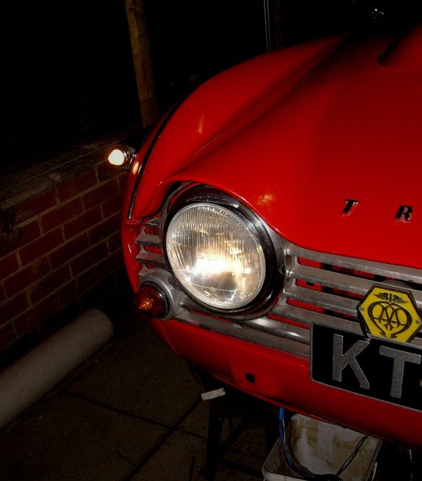
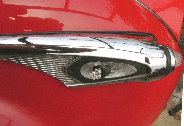
^ the result is quite unobtrusive, even on a 1967 car, but imo useful in terms of their being more noticeable to contemporary motorists. The original but tiny side lights were bright enough but they offered little in way of 'distance perspective' to most other drivers ..whereas a pair of 7" headlamps, even on sidelights, is quite obvious. And that recognition is to me an important safety feature. Just my opinion of course, but for around £10 for fittings and the bulbs, and a few hours work, I think worthwhile.
Cheers, Pete
-
2
-
-
On 28/03/2022 at 09:05, clive said:
cars that have been done. Some have been a disaster, with the fluid seeping out forever after, and damaging the new paint.
I personally did the panels on a car and had this issue wherever there was double skin / panel overlaps that were originally spot welded (ie., such as that car's inner wings). I jet washed the panels and well dried them in summer breeze but still I was to face disappointment after a lot of hard work and the use of high quality 2-pack paints. The car was white and although the paint stayed on, it very quickly yellowed (very unsightly). Possibly not an issue with different colours ? ..I don't know. Problem thereafter is how to neutralise it, as even removing the new paint doesn't get you into the panel overlaps.. I'll not make that mistake again, and will only use the chemicals when it's only single skin ..and that may be brand new panels (before welding in place) such as floors and sills.. which are often painted (typically black) so they don't rust in storage. But that black paint really isn't a very good primer.
Pete
-
Here is one for those who like to up-cycle scraps into very useful tools .
.
I must admit for all the expense of this particular tool, it has worked very well, has avoided a great deal of hurt, and made the job in hand so very much quicker and easier. . .
Anyone guess what it has been so very useful for ?
. . .
. .
no.. ?
a clue is in the photo . . .
. . .
. .
- well here's the answer . . .
 (click on it to view)
. . .
. .
in short ; a backing support for cleaning wiring terminals of grime and their many years of oxidation ...so that the connection reverts back to having minimal losses due to electric resistance. This tool is handy when working in-situ as well as at the bench, and saves the power brush from taking the skin off my fingers ! Useful for cleaning the connections, if they are sound, and/or the stripped bare wires before soldering or crimping.
Pete
-
6
-
-
I'll just screw it onto the underside of air vent or similar resonance box.
-
From the TR forum . . .
On 3/7/2022 at 4:15 PM, Lebro said:An LED compatible flasher unit, being electronic, will have a constant flash rate regardless of the load. They will also be more reliable than an ancient bimetalic type with pitted / rusted contacts ! & yes, the resistor is just wasting power.
My recommendations:
LED compatible flasher unit
https://www.classiccarleds.co.uk/collections/indicator-relays-electronic/products/12v-electronic-indicator-flasher-relay-classic-car-with-oe-click-x-l-p-2-3-pinHeadlamp conversion kit to H4 LED
https://www.classiccarleds.co.uk/collections/headlight-led-bulbs/products/sb7014-sealed-beam-to-h4-led-upgrade-kit-p43t-472-llb472-glb472-bulb-globeOr Headlamp conversion kit with pilot light
Rear indicators
https://www.classiccarleds.co.uk/collections/indicator-bulbs/products/bright-amber-smd-led-indicator-bulbs-ba15s-glb382Rear stop / tail
https://www.classiccarleds.co.uk/collections/brake-tail-light-bulbs/products/2-x-bay15d-red-stop-tail-led-2835-brake-rear-light-glb380-p21-5wSide lights
High quality stuff, & good prices (compared to some who advertise in TR action
)
I don't know of any really good LED conversions for the earlier headlamp units with P36D type bulbs. so suggest switching to H4.
Bob
On 3/8/2022 at 11:52 AM, Lebro said:Hazard warning.
This is easily achieved once you have LED flashers, & compatible flasher unit.
All you need is a 3 pole change over switch, here are two types of different sizes to choose from.
I use the small one, & it is hidden under the dash.
https://www.ebay.co.uk/itm/264269001947?ssPageName=STRK%3AMEBIDX%3AIT&_trksid=p2060353.m1438.l2649
https://www.ebay.co.uk/itm/131898614717?ssPageName=STRK%3AMEBIDX%3AIT&_trksid=p2060353.m1438.l2649
And a small amount of wiring:
This is my wiring, I think your "indicator warning lamp" is wired differently (across the left & right bulbs)
you can just ignore that bit, in which case the warning lamp won't flash when hazards are on.
Or change the wiring to be as above (using the pilot terminal on the flasher unit to power the warning lamp)
Bob
Thanks Bob, I ordered today via telephone ..as I wasn't sure about the bulbs recommended for different sized instruments & the warning lights all being the same, and then I also had a few questions re. minor discrepancies from standard.
I might add, the gentleman over the phone was very patient with me and gave excellent service < Classic Car LEDs. >
In summary, Katie already has LED front indicator bulbs and I'd already bought those for the rear number plate.. so I've now ordered . .
- LED rear indicator bulbs (amber) x2
- LED brake and rear sidelight bulbs (red) x2
- LED instrument bulbs (warm white) x6
- LED indicator warning light bulb (green) x1 NB. I tend to find the main beam warning light bulb bright as it is, so I'm not changing that to LED).
- LED front indicator repeater bulbs (amber / capless on this particular car) x2
- LED front sidelight bulbs (warm white) x2
- LED front sidelight bulbs together with bulb holders to (additionally) fit into the back of the headlamp reflectors (warm white) x2
- LED compatible indicator relay (which audibly ticks, similar to the original) x1
All in all a little over £93 inc VAT and carriage.
I think that's good value for decent quality parts, and from a UK company that is there to back-up their sale.
The reasoning behind my spending this - is primarily to reduce the collective wattage of the side lamps and indicators, whereby in the event of an evening or night-time breakdown ; the battery's charge will last four-times longer and in the meantime those lights will be brighter. Of course, in everyday running, the power not consumed doesn't need to be regenerated either. At present petrol prices
..their lesser power consumption will pay for the bulbs pretty soon !
I'll keep a few of the original bulbs in the boot as spares. IMO there's no need to add the cost of spare LED bulbs which I might never use. Katie's present headlamp bulbs are 60/65w H4 halogen within Cibie reflectors, and I'm happy to leave those as are.
Time-wise to change these is nil, because I'm pulling each bulb anyway to clean connections and to Vaseline the contacts and threads within the bulb holders.
I've also ordered the small switch (off of ebay) as recommended by Bob, so that I might switch the turn indicators into hazard warning.
I'm indebted to Bob for pointing me in the right direction, which has really saved a huge amount of pondering over what might ..or should, be. Thank you.
")
Pete
-
1
-
On 12/03/2022 at 18:50, Colin Lindsay said:
I suppose that's one way of raising the runners when you have no metal spacers. I'll have to come up with something more.... aesthetic... and less of a fire risk. On the subject of wood my replacement dashboard arrived - £25 on eBay - and it's interesting. No varnish at all, maybe even no veneer, but most importantly no damage. It's a great starting point for a restoration - solid, undamaged and bare.


I won't get near it for some time but it'll make a nice project. I'll read the very interesting thread on the forum about reveneering dashboards and then see what finish I want, and work from there.
fire risk from timber blocks under the seats ! ? ..are your curries that seriously hot ?
The grain and colouring of the dashboard looks very much like cherry. That would have polished up to look stunning ..had it been protected from what appears to be fingermarks, mildew & staining.
-
14 hours ago, Pete Lewis said:
a tunnel full of holes
isn't that an interesting literary conundrum !
-
On 12/03/2022 at 16:34, Pete Lewis said:
cut and measure to make new access points
the gear stick remote bolt is almost done already
speedo drive
oil level filler plug
when done there will still be some tunnel left
but it save taking the blasted thing out for silly jobs
Pete
Don't know if it is relevant to your model of car, but the day after I refitted my steel one in place someone on the TR forum, someone piped up to suggest I cut an access hole for the starter motor's top bolt. Now he tells me !
Pete
-
Hi Y'all.
I've had a bit too much fun this past week redrawing the TR4 wiring diagram into Autocad, only to then find out that the TR4A has quite a few differences. It is very remiss of the workshop manual and of Haynes, not to include one for this model of car. after all they did make more than just a handful. I have a copy of Autowire's wiring diagram and have noted various comments about the couple of things wrong in that, so in time, I'll get mine correct.
I think classic cars were only ever invented to try and teach us patience and understanding of another's perspective. The former I'm a persistent failure, and although I do have an appreciation of the design and build practices of these cars - I still find it infuriating when the space lacks just 1/4" extra to get a finger or tool onto fastening.! Old Brit motorcycles are generally much easier to work on.
- - -
Anyways., much of what I'm doing right now with Katie is simply the result of five decades of humidity and heat cycles having hardened insulation on the wires to the point where it has cracked or else where a connector on the end of a wire has worked loose (most likely 'metal fatigue' due to prolonged vibration &/or excessive bending or pulling of the wire into the connector). Credit though must go to those who made these wiring looms. The quality of materials and the way the joints were made, is really very good ..not least insomuch as it has lasted so well and ..in the most part, will continue to safely and efficiently serve its purpose for many years to come.
50 years on though., with the grime of humidity & dust and the inevitable oxidisation of the metal of the connector - I'm sure most every wiring joint on the car would measure excessive resistance. So.., dim lamps, poor charging, poor wiper and heater-blower performance, and then wasted fuel (after all - such inefficiencies always have to be paid for) ..as well as the potential fire risk and frustrating reliability issues either when everyone is watching, or else it is cold, wet, and getting dark !
It's a time consuming business to pull each and every wiring connection, and to pull back their end insulation sleeve and to check, clean and Vaseline every one, but if I don't.. then the piper will at some time have to be paid.
Fortunately I didn't have that many home-crimped connectors on this car, but almost without exception those that
arewere on Katie were loose enough to easily pull off. I really do despise those things.I've (professionally) designed a number of car and yacht looms myself, and so can appreciate that Triumph had to design the loom for different market configurations and equally for expediency during assembly. So while checking and cleaning each wire, I'm also making minor adjustments according to my own criteria ..of being the driver. I stress that I'm moving things around ..not because they are needed, but rather to suit my personal preference of ; having a tidier engine bay, and to order the routing in such a way that it is simpler &/or where any future fault might more easily be traced. I'm also making a few changes according to my own ergonomic preferences and personal taste.
The changes I've made (..or am in the process of making) are ;
- control box (voltage regulator) moved to now be under the dashboard, together with the fuses. This saved a host of wires having to go through the bulkhead grommet and then back again. It also moves those items away from the engine bay side of the bulkhead (next to the pedal box) so that I have a clear shelf to put a tool down. Those items are less likely to have their connections knocked, twisted, etc, or shorted out by a metal tool. NB. each connection on both the fuse box and the regulator were not insulated, but now each are.
- Like wise with the brake light switch. It's a pull type with a spring, which probably dates back to the 1950's as it came out of my box of motorcycle switches. That is mounted onto the pedal box's rear fastening, onto which the steering column brace is also secured. Again its wiring is now direct.
- And the bonnet release cable has moved to a new bracket too. The 'new' bracket was formerly an aluminium coat peg. and it's screwed onto the bottom of the air vent trunking, which is very much easier to reach than where it was. The bonnet release cable is now 10" shorter and a smoother run through the grommet behind the pedal box to curve around the clutch master cylinder . . .
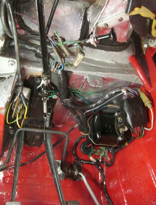
^ speedo & bonnet release cables rerouted. The fine wire to the seen to the left of the master cylinder is an emergency bonnet pull. The original solenoid was removed because Katie has a hi-torque starter with a built in solenoid, and the two electrical wires ..from the ign switch and ammeter to the battery lead (seen under the bonnet latch) are yet to be dealt with.
- The wires to the dynamo now come through the bulkhead under the steering column (the hole was already there), and runs forward underneath the throttle linkage brackets within high temp (silicon rubber ?) wrap to help protect it from the heat of the exhaust manifold.
- The wiring to the headlamps, sidelights &indicators, and to the horn - now run over the top of RHS inner wheelarch, passed the bonnet-stay bracket, then dropping down to the lamps, and across the engine bay to the LHS below the grille. I'll only be having the high-tone horn (sound carries better than the low tone) and that is mounted low-down on the inner wing, by the front LHS body/chassis mount. Just the one horn is rated at 3amp (which is less than that of the earlier cars) and as I'm not going to have a horn on the RHS of the car, I can also be rid of the relay and its nasty nest of wires that sit perched on the suspension tower.
- The wiring from the ignition switch to the coil, and that from the temperature sender to its gauge, now run down the LHS of the engine bay, clipped to the rev-counter cable which now also goes through the bulkhead on that side.
- The speedo and rev counter instruments have switched their positions on the dashboard ..so their cable runs are smoother. I don't have a navigator who needs to see the speedo, nor a wife who likes to keep a check on my road speed.!
- Katie's veneered dashboard was looking dull and generally 'very tired'. I don't think it bloomed with living outside (even in a poly-tunnel). It's plywood was twisted when I bought the car and as I unscrewed it I noticed it was de-laminating even in its core. All things considered, it was overdue retirement. I've always preferred the white dashboard of the early TR4 and so will at some time explore that option. In the meantime (..during this Saturday's breakfast meeting) I acquired a TR4 centre console from my friend Rich ..many thanks to him for that. And rather than pull the car further apart at this time, I'm leaving its TR4A metal dash in black. NB. it's been crudely brush-painted at some time by a prior-owner and although I was intending to cover it in leather-effect vinyl.. for moment and for visual appraisal - the black paint will serve my purpose. . .
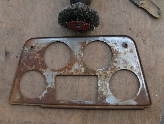
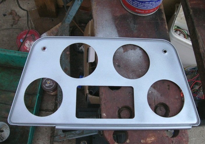
^ after a scrub upto clean off surface rust and a coat of zinc on its back face, the central console was good to go.
^ That looks OK ..I think ! ?
Tbh., I like to think of the Triumph TR4 (yes even the 4A with its 'more compliant' rear suspension) as a rather crude seat-of-the-pants type driver's sports car, rather than the smoker's bar of a gentleman's club. Accordingly, whereas I revere the book-matched veneer dashboards, door and A-post cappings, and fold-out tables in a classic Jaguar saloon, or Aston or Bentley ..I've never felt it looked honest in the Triumph. Hey ho., we're all individuals and even my own personal taste is not a crime !

No disrespect to those who have it in their cars, but I never was keen on British Leyland anti-glare (read dull) teak. Purely by coincidence, at the breakfast meeting on Saturday one of our local TR6's had black kevlar-effect dashboard ..which I thought looked pretty cool. I would of course have preferred the tactile feel of kevlar as well but hey that would be going a bit OTT.
Anyway back to my tasks in hand, I've cleaned up each of the connections on the back of the instruments but I've yet to clean those up on each each of the wires. Monday's job I think, after I've done some paperwork and paid some bills ..if only to get them off my desk. The ashtray is a dummy plate. I'll make, or look out for one, in due course ..no urgency though, as I don't smoke. I guess I'll make a glove box door, and then I'll also want to fill in the 1/2" gap between the centre console and the switch plinth. More jobs to add to the list.
I think finally for today's report ..
- I've positioned a 3-position pull-out type TR4 light switch on the right of the steering wheel. I really don't like the column switches on the 4A and so the steel dashboard already having the hole there and, again my friend Rich helping me with the supply of a good switch on Saturday, I've put it there. I've yet to shop for a knob to go on this switch, but it's a really convenient position just there, and yet the padded roll on the bottom of the dash will prevent it from getting knocked as I swing my legs in and out of the car. I'd like the overdrive column switch to be on the LHS of the steering column. I'm not sure but it may be there on a TR4 ?
Well that's enough for today, Again i bid you a very pleasant Sunday,
Pete.
-
2
-
hi Mathew, thanks and yes.. by the end of this month.
Pete
-
- Feedback on the TR Forum . .
On 27/02/2022 at 08:28, BRENDA1 said:ExpandMorning Pete, looking good you could always go rally style and have no carpets. Your getting there then you can get out and about. Took the hardtop off Brenda as hopefully summer is on its way then we’re going out for a short run over to Lyme Park for a walk round the house & gardens. (It’s so close and it appears Carole has never been) have a good day.
Mike redrose group
Brenda's looking fabulous Mike.
I do look forward to getting such a back-light (mine is in GRP) fitted to Katie, and then of course trying to sort out the Surrey top to fit with the TR6 windscreen header rail.
Yes to start , while I sort through teething problems, rally style with no carpet over the tunnel would make sense, perhaps just rubber floor mats. Carpets can be fitted later.
On 27/02/2022 at 11:25, AlanG said:Looks good. Worth having access hole for the upper starter motor (bolt ?) though.
Alan.
Thanks. Good advice Alan, although I do wish you'd mentioned it before I painted, insulated, &/or fitted the cover. It would have been easy to have had a grommeted hole just there. The grp cover that was on the car looked to have been smashed in that place, and then was gaffer-taped over. I didn't realise that it was from where the p.o. replaced the starter motor.
On 27/02/2022 at 11:54, stuart said:FWIW Sidescreen cars still had the rev counter cable crossing the engine compartment. They just changed sides with the speedo early on in TR2 production so navigators could see the speedo.
Stuart.
Thanks Stuart, Looking at photos on the internet have clearly misled me, perhaps because so many are LHD !
- - -
Following on from the heat shield over the dynamo, and before I refit seats in the car ..this past week I've been looking at / working on Katie's wiring.. The were several reasons for for tackling this now, working under a poly-tunnel during the cold-damp weather
..which in short (pun intended) come down to safety, reliability, and my own preference.
From a personal point of view, I have seen a couple of cars burning. one was a fibreglass bodied Reliant which burnt with such ferocity that it was frightening. The other was an XJ Jaguar ..famed for electrical faults because of the mass of wires and their duplication (in the manufacturer's hope of improving reliability). And then of course I had a small under-bonnet fire with Katie, when a pot of brake fluid was left on the exhaust manifolds, after her clutch release mechanism had been replaced. Fire is a terrible prospect.
Poor reliability is simply a pain in the archives. Even a well maintained car can fail an MOT because the horn or washers, or a lamp not working. The latter also tends to attract the attentions of the Police ..which on the whole I like to keep on the right side of. Naturally, because more electrics are used in the winter months and in the rain, heater, wiper, lights, etc, so then the electrical loads on the whole are greater and the likelihood of fault is greater ..all to often occurring in the cold, dark and wet. And of course in the cold weather, the starter is working harder to turn over more viscous engine oil and then with lights on the charging system is working close to its capacity. .
My third point was own-preferences. I find life easier when there's logic in the wire's route, but of course Standard-Triumph had to make compromises for economy, ease of production and commonality of parts for left and right hand drive cars ..destined to different markets. I also distrust home-crimped connectors, and insecure/ unsupported wires that drape or swing around loosely and chafe. And then again clutter and unsightly wiring, and heater pipes, drive and control cables crossing over each other in the engine bay.
I find a neatly laid out engine bay is easier to keep clean and tidy, easier to see when something is not quite right, and offers better access for maintenance (I lost count of the number of times my right sleeve snagged on the exposed terminals of the horn relay when I was working on the dynamo, its mountings and shield ..before I removed it !). I also find neat engineering is somewhat more pleasing. But then I also have personal preferences in terms of things like hazard warning lights, electric screen-wash, and lights of an appropriate brightness ..now that other night-time ambient light levels (other vehicles and street lighting) are so much brighter than they were 50 years ago.
Even a cursory check of Katie's wiring revealed that important (read un-switched live and heavy current) connections had failed. For example two of the large wires to the control box very easily pulled out of their connectors, those to the horn and dynamo each had heat-hardened and cracked insulation, and the wires to both the main and dipped headlamps were pinched-through the insulation to expose the copper wire. Many other wires had the end connector with exposed frayed wires to it. I also didn't like the electrical wires going forward being routed in the bottom corner of the inner wing, where any petrol leak would dribble onto them.
Non of the wiring connections which had been home / previous-owner replaced with crimped wore end-sleeve insulation over the connection, so each were exposed to be shorted out. These include each wire to the control box. Even the original connections to the fuse box are exposed. Each of this car's three fuses were 35A, and no connection terminal appeared to have been cleaned and Vaselined when the car was restored 22+ years ago ..so commonly the resistance between every wire and its connection would be high. Throughout the car - that'll add up. High electrical resistance leads to higher currents being needed for the same output, and then the greater the risk of fire &/or failure. It also means more battery charging is necessary which of course is paid for in fuel consumption.
Is the car likely to be safe. legal and reliable as it is.? - Aside from the horn not working, and the control box being of poor aftermarket quality with intermittent connections through its loosely riveted terminals, it otherwise works for now. But imo failure is imminent when damp, corrosion and vibration will take their toll.
So, present work-in-progress involves checking every connection, cleaning off oxidisation (back to bare metal), add insulation where appropriate, with Vaseline brushed in every joint before reassembly (to lessen further corrosion), and then of course securing the wires.
That aside I'm in the process of moving a few things . . .
. .
^ In terms of own-preference (logic in routing and a clearer engine bay) and in order to keep more of the electrics in a kinder environment, than an engine bay, I've chosen to relocate the control box and fuses to under the dashboard, in a line back from the voltage stabiliser. At least if there is a fire I'll have advanced warning from the smell of melting insulation ..or my pants being on fire ! Yes there's plenty of room for my size-13 feet under there too. The underside of the bulkhead was repainted and aluminium tape applied over that to reflect light in that corner. And the fuse-box is on a bracket so the fuses face me when its cover is off.
The brake light switch is dangling loose at the moment, but I want to move it to under here too. I yet have to re-wrap the wires, and will use sleeves for the longer runs, and then of course to properly secure those wires.
^ In the engine bay, for the forward wiring (lights and horn) I'm taking the high road over the inner wing rather than through the gully under the carbs. I'm also taking the opportunity to replace the grommets through the bulkhead for new, so noise and fumes are less likely to waft their way into the car's interior.
And I now have a clear bulkhead shelf, besides the pedal box, to put tools down onto.
")
Next I'll be looking into LED side, brake and indicator bulbs. There's a lot of reading (I've yet to do) in archive posts to find out what's what.
My front indicator bulbs are already LED (stamped 1156 12v) with a " 25w 7 omn J " resistor on one side. I also have LED number plate lamps, but for the sake of brightness and least electrical current - I'd like to replace the rest. The car is negative earth. I'd also like to add hazard warnings, and to add additional sidelights into each headlamp.
Cheers,
Pete.
-
1
-
I'm not familiar with the mountings on this particular car but the importance of them is only in respect to 1. holding the alternator secure enough to prevent the belt slipping (but no tighter as that wears bearings out), and 2. to aligning the alternator pulley in the same plane as the other pulleys.
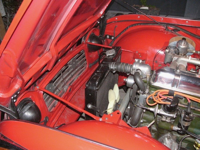
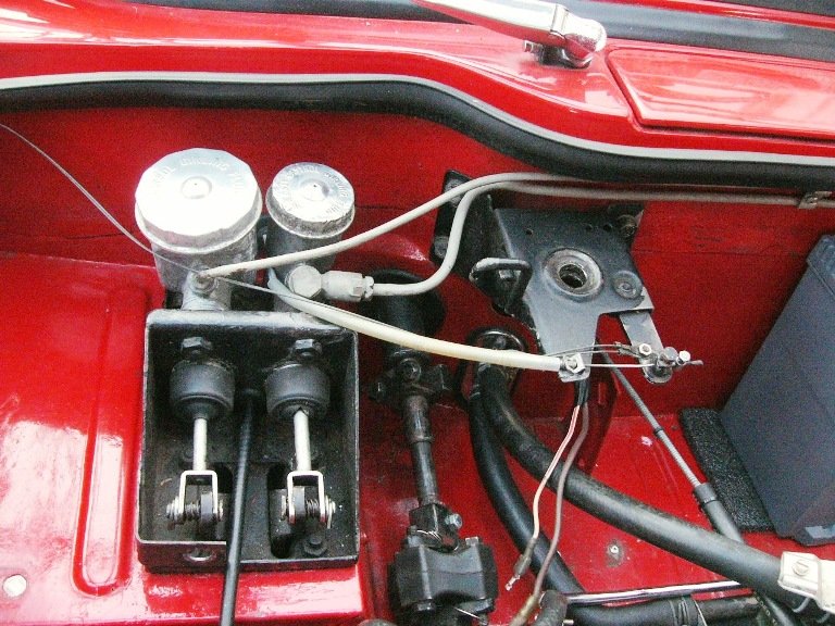
However, I wonder about the alternator's fan. The engine fan suggests that the engine turns anti-clockwise (as viewed from the rear) whereas the fan on the alternator looks to be for clockwise rotation. If I'm correct, that may cause it to overheat and prematurely fail.
Of course, a repeatedly heavily-discharged battery or even a wrong battery size would overwork the alternator. To small a capacity and the alternator is working full wack to keep up with the winter needs of lighting, heater blower, and wipers etc. Too large a battery capacity is again too much work to recharge, should the battery be left to go flat.
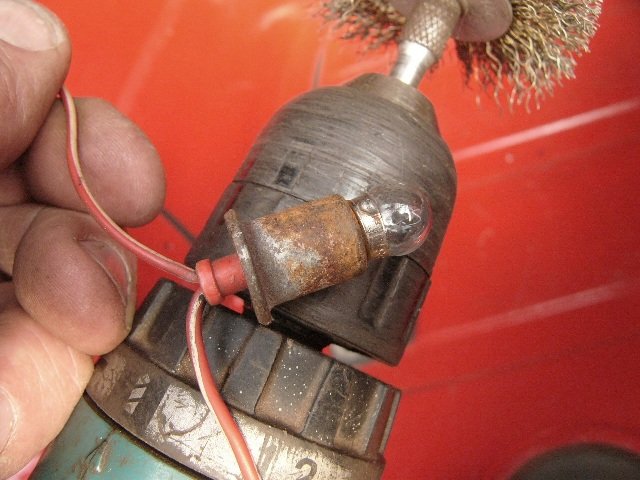
I would also ensure the HT lead was well clear of the alternator case. If that lead is shorting out through the alternator then I cannot imagine what that sort of high voltage would do to it .. possibly very similar to welding on the car while the alternator is connected. What is the other wire resting on it ? ..the one that runs around the front of the engine. Again if grime on the outside of that cable's insulation can conduct electricity, then the HT lead may short through that to the alternator.
Pete
-
 1
1
-
-
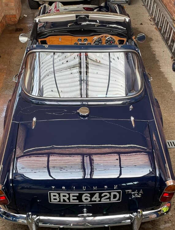
This afternoon saw us pass a milestone in Katie's reassembly
. . .
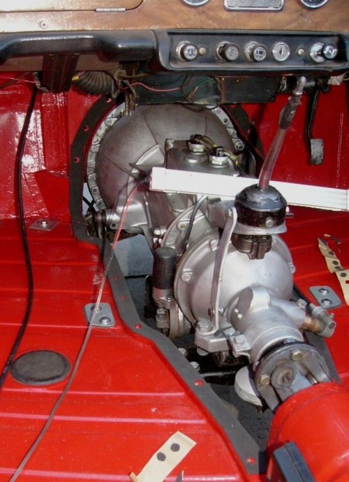
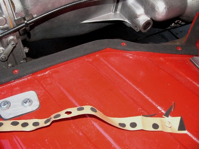
^ I've used 2mm thk x 30mm wide self-adhesive neoprene rubber strip for the gearbox-cover seal. Using a coring knife (as in apple cores) against a block of softwood, the screw holes were 'punched' out as I went along,
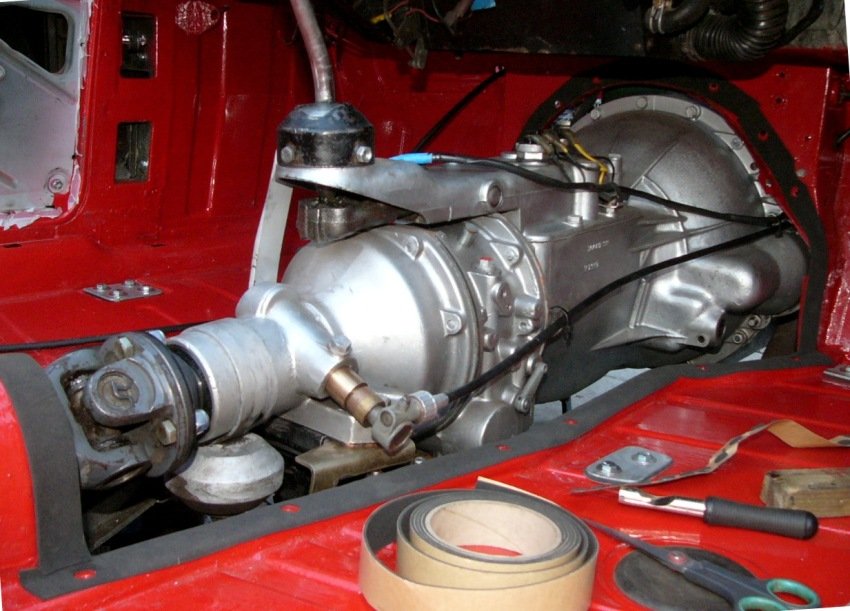
^ forward section in. These jobs always take a little extra time when working alone ..and the bolts, penny washers, and my ribbed-rubber dam (between the engine bay and the gearbox) are fitted from the engine side of the bulkhead and the nut & washers are fitted, with a long reach forward, within the car's interior.
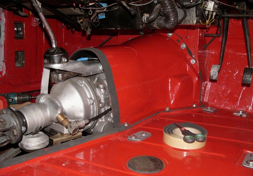
^ yes, indeed, the speedo-drive's access cover still needs to be fitted, and also the self-tapping screws around the panel overlaps (each have been pre-drilled but I don't yet know if they line up with the seals in place).
I'm rerouting the rev.counter cable as well, as it looks unsightly running from one side of the car to the other within the engine bay. I believe the side-screen cars did it this way, so no innovation here ..just a preference of mine.
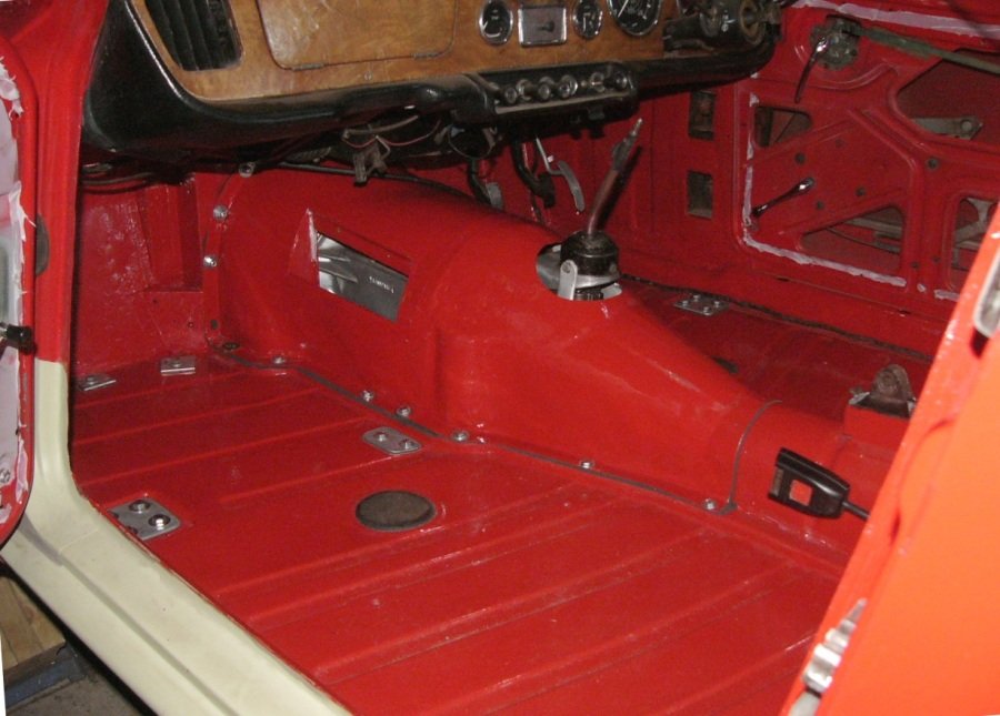
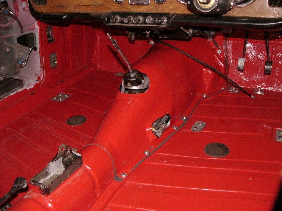
^ job mostly done, but for fitting the back face of the map pocket, the interior trim with gear-change gaiter, and the handbrake lever.
Because I adapted this cover to fit under the H-frame - it's somewhat sleeker than than it was (TR3 shape). It looks, and in steel it ought to be, purposeful .. such a shame to hide it under carpets.
anyway I'm really chuffed that its fit is so very tight.
Bidding you a pleasant weekend,
Pete
-
3
-

 The LED side lights and indicators (..particularly noticeable at the rear) are much brighter, and now thanks to TR3-Bob (of the TR forum) I even have hazard warning lights.


")

 Oops !!

")


")


")

That was a year that was..
in My Triumph Restoration Project
Posted
Peter, to be honest I didn't look at the needles closely but I'm sure they had black pointy tips, which suggest Viton. They came from a long established carb-rebuild specialist - Southern Carburettors (..very quick delivery too) who ought to know what they are doing, rather than buying from a shop keeper.
If you have fuel smells within such a tight speed range, I would tend to think vehicle aerodynamics are emphasizing what may be no more than fuel tank vent vapours being drawn into the car. Perhaps the pipe from that vent needs to be longer or re-routed.?
Pete