

Bfg
-
Posts
1,201 -
Joined
-
Last visited
-
Days Won
45
Content Type
Profiles
Forums
Blogs
Gallery
Downloads
Store
Events
Posts posted by Bfg
-
-
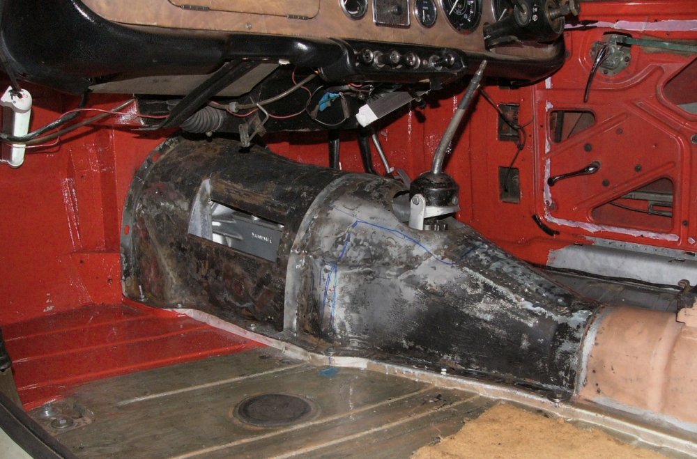
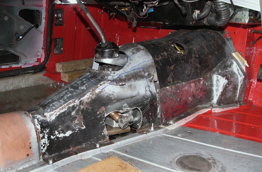
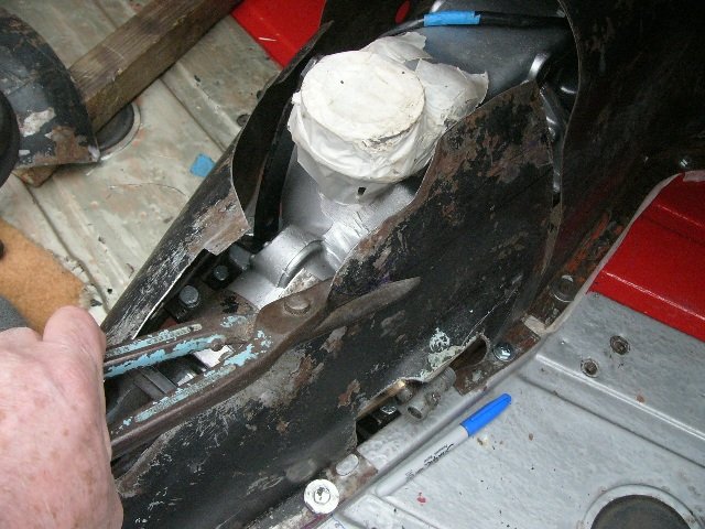
It's a busy time of year but I'm now close to finishing up on Katie's gearbox cover ..
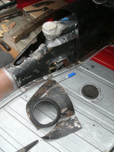
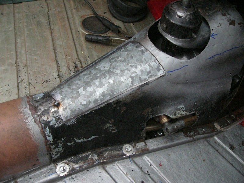
Firstly though, I had to close over the speedo drive. . .
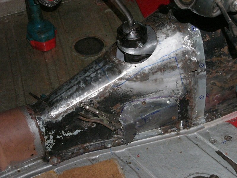
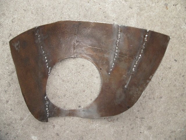
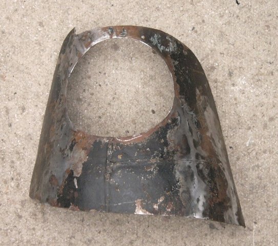
^ again trying to make things close fitting / less intrusive into the interior. There was a little more work in making this a removable access cover, but really not a whole lot. My difficulty was in shaping the thin material (reclaimed panel from the back of a boiler) as its steel was far less ductile than the original cover, and so somewhat reluctant to shape into a neat compound surface.
^ I also drilled the screw attachment holes between the two sections of this cover ..and those for attaching to the bulkhead and again to the drive-shaft tunnel. Then blanked the (TR3 gearbox dipstick ?) hole in the top of the forward section and the small one for the oil-filler, as well as several carpet fitting holes, before adding a few penny washers to where this cover's bottom flanges were a little frail. ..and of course generally cleaned things up . . .
And then to add a coat of paint (again I'm using POR-15), followed by just a little seam sealer . . .
^ Strictly speaking that ought to be fine, as it'll all be under carpet ..but by special request . . .
On 12/12/2021 at 09:33, BRENDA1 said:Hope your going to paint it all red.
Mike - Redrose TR group
..If you like Mike
")

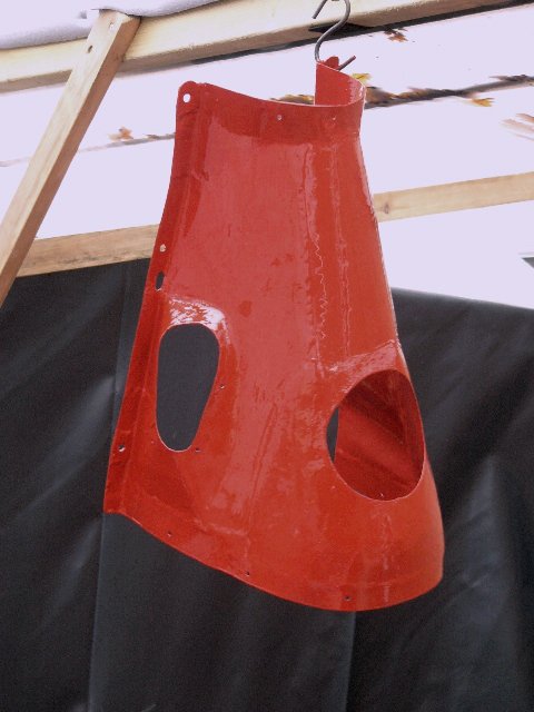
^ No prizes for this panel work and paint I think, but it'll serves its function.
That's it from a damp and chilly Ipswich, where the paint is slow to dry.
Bidding you all a good evening,
Pete
-
 3
3
-
-
You've tried foam bathroom cleaner but I wonder if the foaming upholstery cleaner might be more effective. I've first used it on seats and steering wheels that were about to be scrapped ..I think a prior owner was a mechanic and brought his work home on his hands and overalls, anyway those seats came out looking like new. The foam of course getting into the grain / all of the corners. Otherwise are there no alloy cleaners for wheels ..which get embedded in brake dust and sometimes splattered with grease and tar. ?
Pete.
-
Thanks,
I've used aluminium faced sound deadening / anti-drum pads extensively and then sheets of neoprene in the Citroen I restored, but to be honest the car was a pressed-steel drum and even when done was not particularly quiet . . .
-
When painted over I think it ought to look fine, and then of course it'll be carpeted over too. I'm thinking of fudging together a 1/2" thick felt-within-plastic type horse-blanket ..to lay over the gearbox before I fit this cover, rather than stick-on insulation either on its underside (which can get very grimy) or outside (which takes up interior space). And then to use just 1/4" foam under the carpet to soften it's touch. Any thoughts ?
Pete.
-
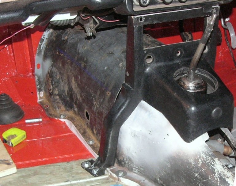
Having established the steel g/box cover's shape and fit, I next needed to weld it together and at the same time get down to details ..like the overlap between my front and rear sections . . .
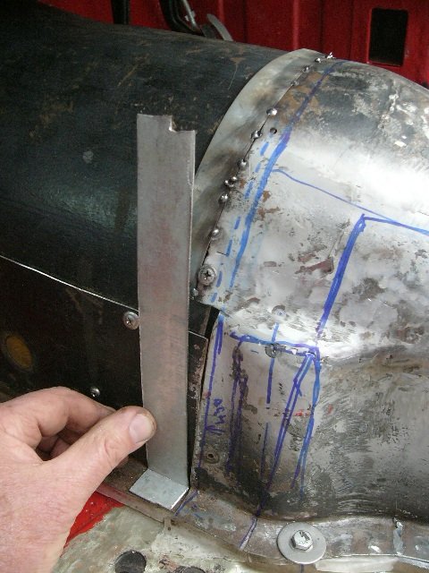
^ raw material came from a pair of household radiator mounting brackets ..naturally reclaimed from a skip.
")
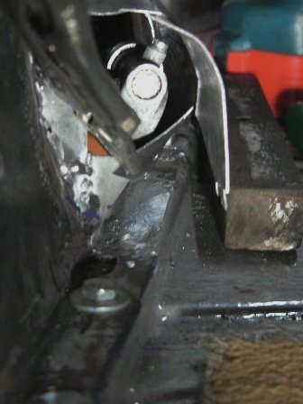
^ getting close.. with the overlapping flange added (although not yet drilled for its fastenings), a flange added under the speedo drive, and of course the forward section's top and RHS welded together with its maximised footwell width and sorta clutch-foot rests. I still need to close the hole in the top as I can't imagine access is necessary there. The cover over the speedo will, I think, be screwed on. But then again.. how often does one need to just get to the speedo cable ?
On the LHS of the cover, I wanted to add just one more
 little detail. . .
^ before the overdrive and its solenoid, there's a fair amount of space between the floor and the gearbox. The block of wood you see pictured is 46 x 98mm in section, and I've screwed it there, level with the raised flange of the floor edge, to see if it would come out passed the O/D solenoid. It did, and so . . .
^ 4-1/4" (110mm) above the bottom flange I formed a rolled edge, for panel rigidity.
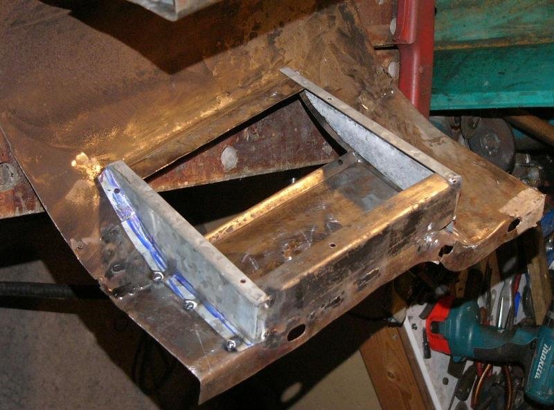
^ The top cut-edge was joggled a little before I fabricated the sides of a simple box. Although presently only tacked together - it's already a surprisingly stiff structure. My intent is to have a plywood lift-out back panel ..where just two screws need be removed for good access to the gearbox filler / oil level plug.
^ When the back of this box is in place, I'll have an extra storage bin. It's not huge ..but I think it'll come in handy, whether for documents or else for a windscreen squeegee & cloth. Its inside dimensions are ; 1-1/2" (40mm) front to back x 8-3/4" (225mm) long, with 4-1/4" (110mm) up to the rolled edge, and an average of 7-1/2" (190mm) vertical from its base to the curved top cover. If I fit a fabric liner, then I can pull out anything 'lost' in the bottom.
That's it for today. I bid you all., a warm and pleasant evening,
Pete.
-
2
-
-
On 12/12/2021 at 08:11, PeteH said:
HI
Looks like it will be a decent job when finished. For myself, I think I would perhaps have looked at beefing up the F-G offering!, as being a lot less of work involved?. Not withstanding, I am still admiring your skills in a clearly non workshop environment. Well done!. P.S. how is the Trailer/camper coming on?.
Pete
Hi., what you're saying Pete is that it "looks like it will be a decent job when".. under sound deadening and dark-coloured carpet ? just kidding
 .. Thank you.
Fibreglass is a wonderful composite material ..which is incredibly strong for its weight (especially in tension) but it is not in itself a very stiff material, nor locally (around bolt holes) very strong. Any stiffness comes from its formed shape and how well it is bonded to the adjacent structure.
So, in my considered opinion.. "beefing up the fibreglass offering" would miss the point. Which is, when bolted in place - a steel cover structurally-extends the driveshaft tunnel (a pressed-steel u-sectioned backbone, fastened on either side to the main chassis rails) to the bulkhead and forward body mounts, ie., it fills-in the considerable length of car where there's a gaping-great-hole in the floor, and door openings & no-roof compromise body rigidity, and perhaps more critically with regard to the car's handling - its torsional stiffness. If one were to think about it.. it's quite bemusing to read of adding anti-roll-bars and the host of 'upgraded' bushes, springs & dampers - when these car's overall structure, all those lovely goodies are bolted to, flexes ..somewhat unpredictably !
In short, the time n' trouble I'm putting into making this steel cover fit well - saves the time and cost in suspension upgrades. Aside from polybushes Katie's suspension is of standard specification. As are her wheels n' tyres, and steering.
Pete.
-
After a couple of days off, I did another afternoon's work ..with my doing similar slimming-down of the bulges on the passenger-side's cover. . .
^ Left is what we had, with an inch and a half lateral clearance besides the clutch lever arm. ^^ I've slimmed that down to around about 1/2".
And then, the top part was dropped down a bit at the bulkhead, and an inch or so where the two halves of this cover will meet to fit under the H-frame. . .
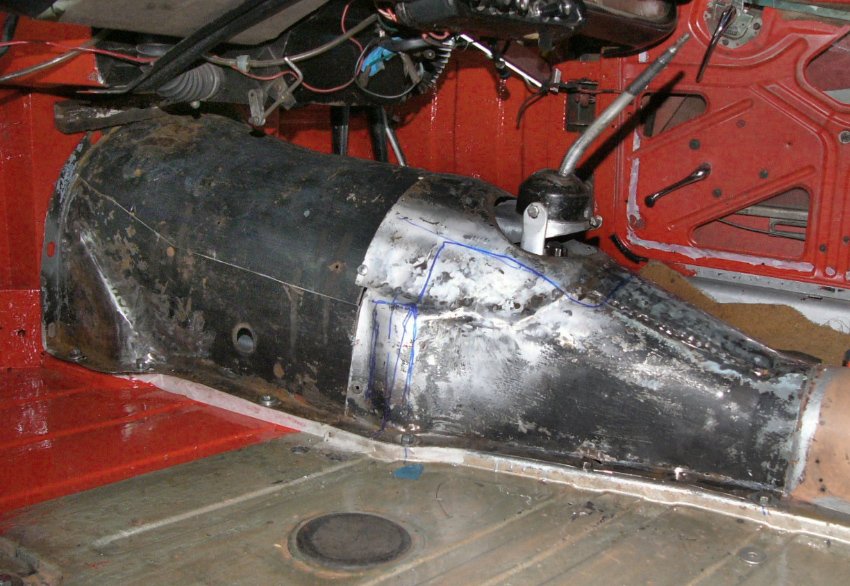
^ its getting very close to looking like the fibreglass cover that was on the car.
^ the top of the front section is presently only held in place with self-tapping-screws, but all-in-all the shape is now as tight to the gearbox as I dare take it. It's still a mighty-great-lump to have inside the car though !
I hope to get things welded tomorrow ..but with noise abatement courtesies (..what with respecting neighbours an' all), I won't be able to fettle those welds, or to make the overlapping flange. That'll just have to wait until next week. So for the time being..
I'll bid you once again a pleasant weekend.
Pete.
-
2
-
-
Suggested on the TR forum . . " any scope to dog leg the pedal(s) to the right by 1-2" to give your left foot more room as it is you might end up riding the clutch."
And my reply which I'll share with your good selves, simply because I drew up an illustration that might be pertinent to owners of other cars . . .
. . . Thanks Gents. That is a possibility, but ergonomically a disaster.. The clutch pedal on my car already hangs 1-1/2" to the right of the steering column, which means our foot, knee and hip are skewed some 7-1/2" to the right, as we push down on the clutch pedal, which swings in-line with the axis of the car.

^ TR4A seat to clutch pedal configuration. The hip's ball joints indicated by the two red circles. With the seat in its further back position, there's a 12.6 deg skew of the hip and foot to the clutch pedal ..which then pushes down square to the car. For those with the seat 100mm forward this angle increases to 14.3 degrees, so perhaps the clutch feels heavier than published figures might imply ? Either way, I'm sure left-hand-drive cars are considerably better in this respect, but then their brake pedal ergonomics are worse.
Although the human body is incredibly adaptive, particularly when young &/or fit n' agile, it may be that some of us (in the latter-stages-of-life) experience some discomfort (particularly in the hip or as a back-ache) after a lot of stop/start driving in traffic.
So ideally I would very much like to move the clutch pedal across to the left, rather than to the right.
Pete.
-
17 hours ago, Mathew said:
Getting there, what are you going to do for heat and sound proof?
..haven't really looked into that yet, but when I bought the car it had 1/2" thick felt under the carpet, over a crappy fitting fibreglass cover. My first priority then will be to make this cover sealed.. And similarly the hole through the bulkhead.
I've only driven the car a few miles with the top up, so heat and sound proofing hasn't been an issue.
 Someone was saying just the other night that they sealed off the gap between the bulkhead and the bellhousing on their Spitfire. Beforehand the gear-change lever got hot, thereafter it didn't. That seemed to be a rather neat and compact solution.
Pete
-
^ Those Gilbow shears are really great. I've had mine for I-don't-know-how-many years. I've had four other pairs of shears (one is left-handed) but these and my small ones are the ones I use mostly. Good tools are worth their investment. They cut straight, handle corners well and have remained sharp, despite some hard use.
- - -
Today I didn't get a lot done, but still a little progress in the right direction is better than things going backwards
") . . .
. . .
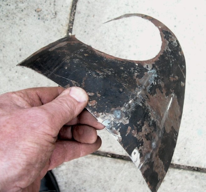
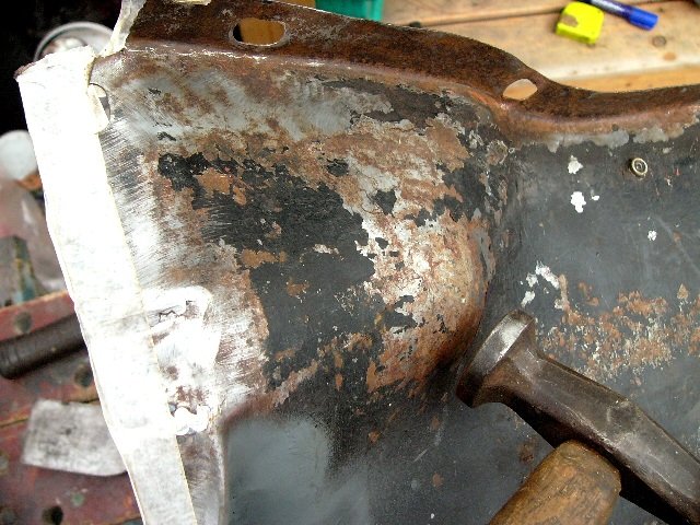
^ I started by cutting the RHS of the forward section, in much the same way as I've done on the LHS., and then you'll spot some vertical cuts too. There is method in the madness, although you may have to be just a little crazy to see it !

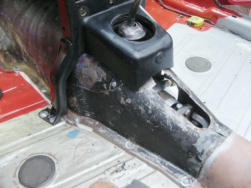
The second photo is the bulge over the starter motor, which I had reworked before, but wasn't happy with. I'd like a little more width between the clutch pedal and this panel, and that would only be possible if I cut and reworked it again. . .
^ Oh my.. this was taking things to another level. I've cut and twisted the steel to follow parallel to the bellhousing's starter bendix bulge. This give me a 2" wide step / footrest just about the clutch pedal height, and then a second narrower step in from the flange. The latter I may add to (width wise) with a bolted-on clutch footrest for my foot down alongside the pedal (below). . .

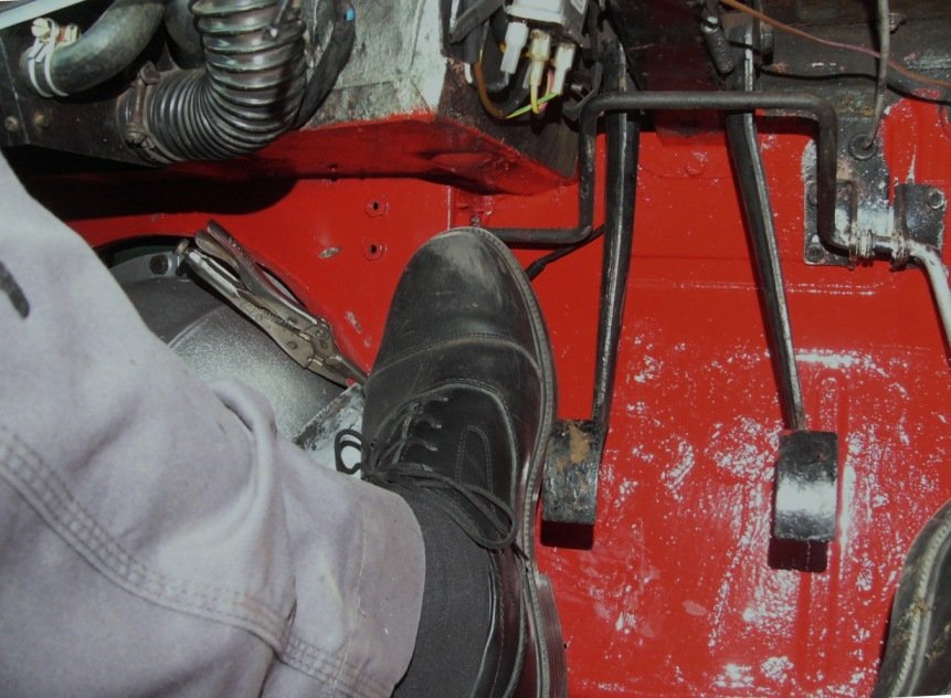
My size 12's now have an inch more width. Not as much as I'd like, but still it is better (..for me) than it was.
BFG ( ..Big footed gxxxx ?
 )
)
-
1
-
-
On 12/4/2021 at 11:29 PM, Bfg said:
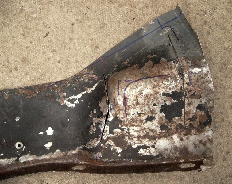
Next, I needed to recreate the top of this rear section ..the bit I'd cut-off. I opted to straighten out / redress the original and tack-weld over Tommy's cuts, because I wanted this part's curves and hole for the gear-change rubber and also the original transition shape ..from rising up from the prop-shaft tunnel to leveling off over the gearbox. . . .
moving on . .
^ I needed to redefine the size, curvature and position of the gear-change gaiter
^ Looking more like a piece of medieval armour than part of a TR4A ! ? But now ..at last, I was close to where I would started, had I modified this cover without Tommy's help..
^ the gaiter centralised with the gear-change mechanism, and the top part of this now positioning lower to clear the dashboard support / H-frame.
^ I shaped a little more clearance around the overdrive's solenoid, and then above that the cover has to taper in quite sharply to get under the H-frame. The gear-change extension's anti-vibration strap had previously worn through both the gaiter and the old fibreglass cover, so this time I smoothed the corners off.
^ raw materials, from the back of a boiler, relieved from the skip ..Put to good use I thought.
^ I'm slowly but surely getting there. My hope is still to not use the H-frame, but if scuttle shake is pronounced and otherwise unable to be resolved.. then I need to know that I can fit it.
There is still the bulge over the speedo cable to make, and these flanges need a few repairs around their bolt holes.. but for the time being I'll move on with the front section of the is cover to bring its height down to match. . .
That's it from sunny Ipswich this morning, Have a good'n.
Pete
-
2
-
-
Nice job Mathew.
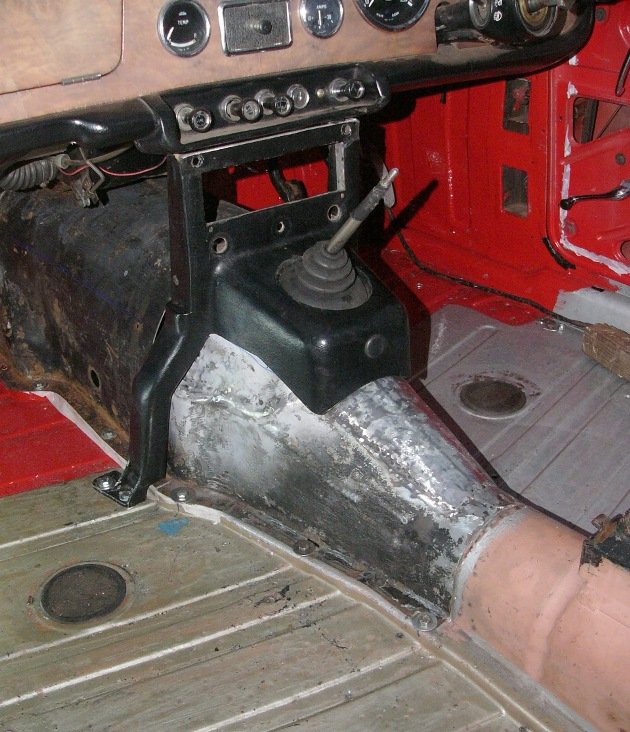
") Yes, in steel it will add a backbone the body tub. Getting things neat around the gear lever is awkward ..as is the compromise (particularly with the Triumph gearbox with its extended linkages and other bits poking out all over the place, plus the bulk of an O/D and its solenoid) in trying to make things tighter fitting (for the sake of interior space in a small car) and the smooth lines required for neatly fitting carpets over. Clearly the RX8 gearbox is much neater in that respect.
Yes, in steel it will add a backbone the body tub. Getting things neat around the gear lever is awkward ..as is the compromise (particularly with the Triumph gearbox with its extended linkages and other bits poking out all over the place, plus the bulk of an O/D and its solenoid) in trying to make things tighter fitting (for the sake of interior space in a small car) and the smooth lines required for neatly fitting carpets over. Clearly the RX8 gearbox is much neater in that respect.
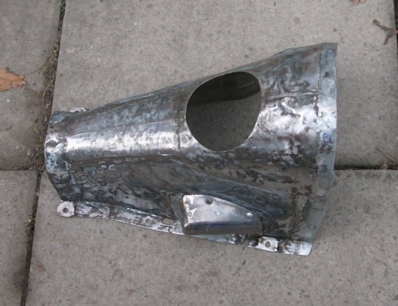
The cover I'm making will eventually be in two parts, and bolted together ..with the rear section easily removed for access to the solenoid, the speedo drive, and the driveshaft's front UJ. The fibreglass cover I'm replacing also has four local-access covers. Unfortunately I'll still need one for filling the gearbox oil.
Pete.
-
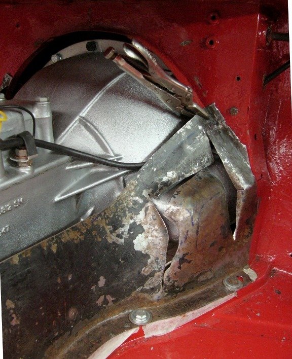
Christmas tunes aside.. I've been having a bashing good time these past few days. . .
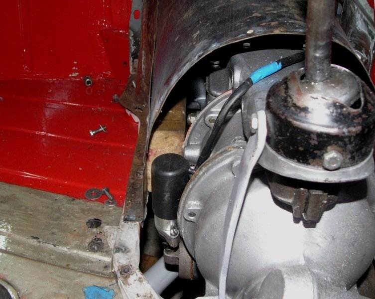
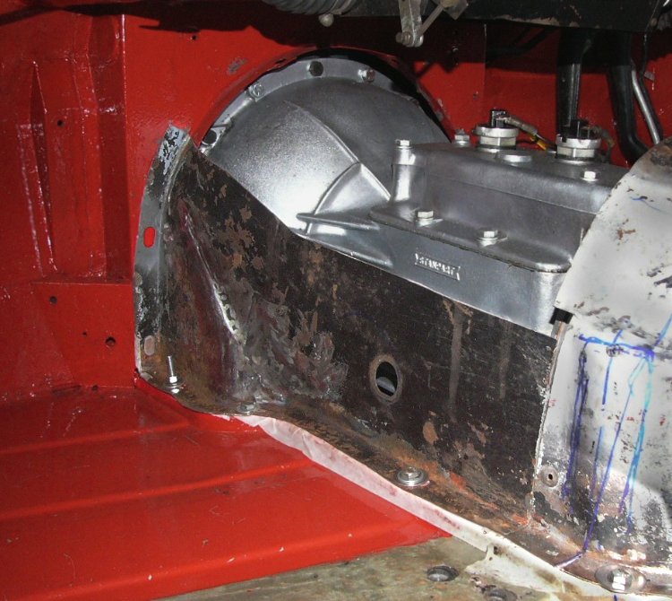
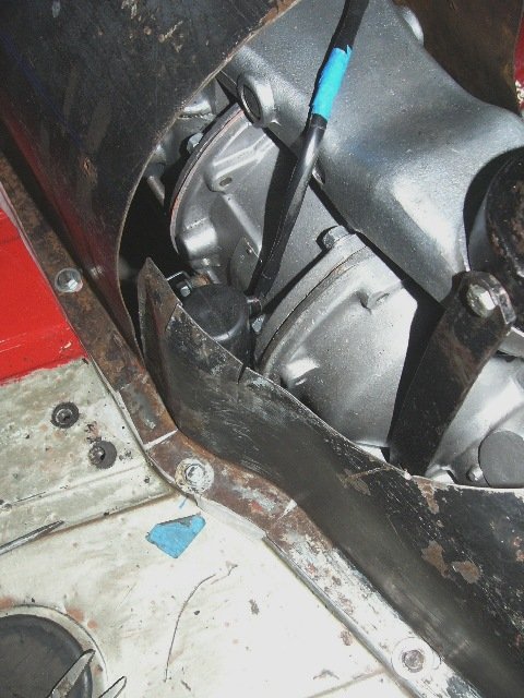
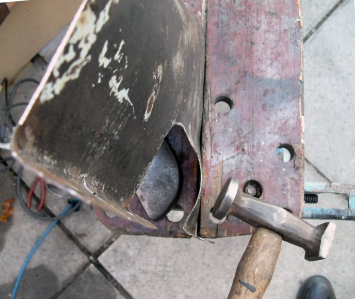
On the TR forum a contributor, Peter W, had helpfully pointed out that the TR3 gearbox cover would foul the cast shape of the TR4 bell-housing ..which has a more pronounced bulge over its different starter bendix. That part of the panel would need reshaping just about here . . .
With the cover back in place and bolted down as best I could (it was being held away just a little in this front corner, I could tap on the outside of the cover to find the centre of the hard contact sound of the bellhousing's starter motor bulge
.
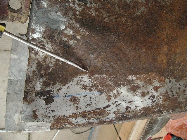
^ with the cover back in place and bolted down as best I could (it was being held away just a little in this front corner, I could tap on the outside of the cover to find the centre of the hard contact sound of the bellhousing's starter motor bulge. I marked that, and then transferred the mark to the inside of the cover with a centre-punch dint. I also measured the bulge from the floor rim and from the bulkhead, to know its extents. I then stretched (read - hammered ..but with awareness !) the metal locally to form a corresponding bulge. . .
^ checking from the inside ..again using the camera to see where the head couldn't possible get into, the clearance now created between the bellhousing and the cover. In most places I'm leaving more of a gap around the gearbox, for sound insulation, but this is right next to where my size 12 brogue is trying to find a resting place ..other than on the clutch pedal or bulkhead mounted headlamp-dip-switch, so I wanted to keep things tight. BTW., the fibreglass cover that was fitted rubbed on this corner which I think might have been Katie's #287 rattle n' clatter. With foot room (width) in mind.. I then did a little more bashing & cutting just forward of this bulge. . .
^ This is yet to be be dressed (smoothed), but I'm sure you can see the indentation forward of the starter motor's bulge, and also that I've cut-off the flange, which extended passed that corner of the bulkhead. The TR4 cover's fastening flange, projecting back from the bulkhead is still there, so the cover will still have a seal in that corner. And although I may have only gained another 3/8" to 1/2" of width, it all helps make the car more comfortable for me.
- - -
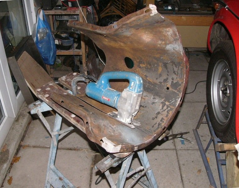
Next up, having got this front section of the cover to fit the floor and bulkhead nicely, would be to tackle the cover's rear section - which is to fit between this forward section and the propshaft tunnel. But first I had to overcome a psychological hurdle ..to the point of it being utterly demotivating . . .
On 21/03/2021 at 14:29, Bfg said:ExpandHowever... Tommy seemed to be struggling with simply getting on with the job. It was his job and so I tried to only suggest client instructions to what was wanted. In truth I was enthusiastic by the fit and I just wanted to get on and do it. His rolling & smoking cigarettes while he was thinking was getting to me ..as indeed was rap "music" out of the transistor, having tea and then toasted sandwiches, and his not being able to find tools. There are no solid work-benches, and two lightweight stands are covered with tools and drill bits ..from however long ago. So anything is done by scampering around on the floor or otherwise hammered over a steel (horse) trestle at the other end of the workshop
According to the photos, we started looking at these g/box covers at 11:40am. And the photo taken ..where the cover was simply cut into two, was taken at 13:12pm ..an hour and a half later ! ..by 16:00 we had packed up.
The cuts (as darts) he'd made to bring the small rear part of the cover lower & narrower (to fit under the H-frame) was let's say "not as I would have done it". Very ugly indeed, horribly hammered, and with just a few holding-tacks of weld to show for 4-1/4 hours work. The front / larger part of the cover hadn't yet been touched.
If I were to let it continue, then it would be a very expensive job (for what I was getting). Perhaps it's a sad reflection on me, but I am not even able to watch someone work like this. After doing things my own way, and just getting on with the job on my own for the past 40 years - I was getting more and more wound up. I didn't say anything but.. I'll not continue with him doing this.

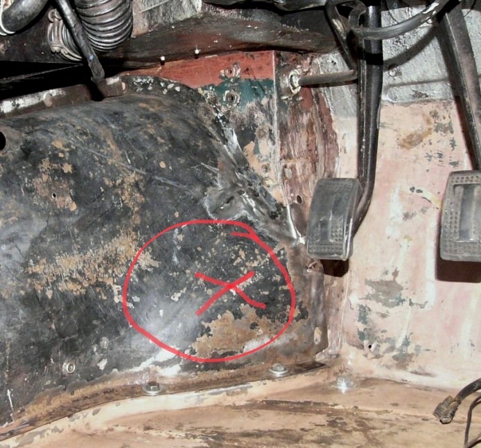
^ Untouched since that day in March, this was how things were when I call a halt to Tommy's efforts. It may seem odd to some, but to me these are abusive hammer marks.
My task for today., was to make this once tidy gearbox tunnel, once again tidy. And for it to be structural. The question was how to proceed.?
I started off by scrubbing out the inside of dirty grease / oily sooty deposits, and the hardened remnants of an ancient rubber or was it bituminous seal. I cannot believe any professional would even start to panel beat something that has filthy crud inside it. How can they see or feel what they are doing ?
I then chose to undo most of what had been done, and so released the tack welds. To clean up overlapping metal and, more readily get inside with my panel-beating hammer and dolly, to redress this panel's shape.. I cut (with my faithful old Gilbow hand-shears) from the bottom cut on the left hand side (seen in this 2nd photo) around in a curve to the long hole.. Not exactly surgeon like, but I'm sure you get the drift. My intent was to try and save the top piece with its original gear-change hole, if only to use that as template.
It took a little while to get things looking like it hadn't been in a crash, but thanks to good quality steel used in the 1950's.. it progressed well. The next stage was then to fit this panel's bottom flange to the floor edge. The TR4 is a little more shapely in these parts ..probably because its squarer seats needed a tad more space, so a few cuts through the flanges would be required. Nothing very drastic but necessary to get a decent fit.

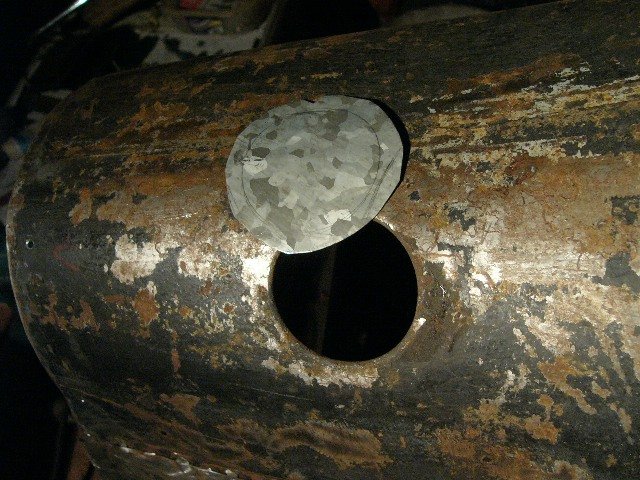
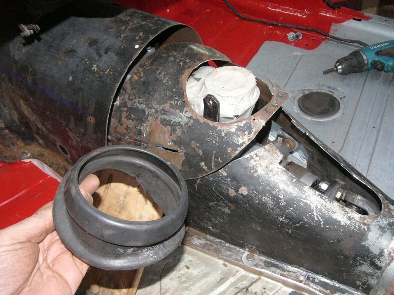
^ I also needed another bulge.. this one is to fit over the speedo cable, which then necessitated my having to refold that section of flange.
While doing these things I was bearing in mind how to re-form it (this section of the TR3 cover) lower and narrower to fit under the TR4's dashboard support / H-frame //and yet for the gear-change boot to be end up in the right place ?
^ the front section of the tunnel cover is clear of the H-frame, but will still need to be lowered at its back-end by an inch and also narrowed, particularly on its LHS. The rear section I reshaped to bring its top considerably narrower. The 8mm thick pieces of wood are spacers to allow for carpet. The cover, where it sits over the prop-shaft tunnel was slit back from what was a grommet hole (..but for the last 3/8") so even that part of this panel's top could overlap and be narrower.
Next, I needed to recreate the top of this rear section ..the bit I'd cut-off. I opted to straighten out / redress the original and tack-weld over Tommy's cuts, because I wanted this part's curves and hole for the gear-change rubber and also the original transition shape ..from rising up from the prop-shaft tunnel to leveling off over the gearbox. . . .
^ I happy that this rear section is beginning to look half decent again. Shame about the extra work but hey that's water under the bridge already ..not least as I'm pleased with today's progress.
Bidding you a good weekend,
Pete.
-
2
-
-
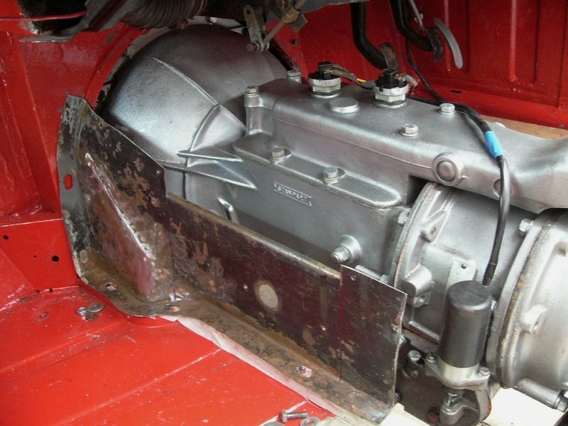
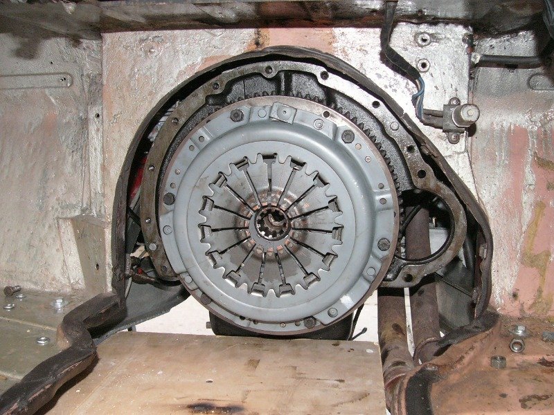
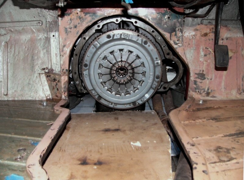
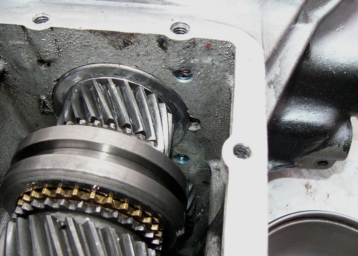
My tasks since putting the gearbox back in, has of course been to bolt it up, fit the gearbox mount, the gearbox rear vibration damper, and reconnect the drive shaft, to refit the top cover (after having filled the gearbox with fresh oil) and to refit the clutch slave cylinder. Bolting the bellhousing up took a little longer than expected as most of the bolts were a little short and I had to do some finding. The bellhousing's underside dust plate (a home made item) and slave cylinder had a weird assortment of bolts and wrong sized washers. I guess it's not really that important but down under I reverted back to UNF thread sizes with nylocs rather than its assortment of BSF's and something else. These things all take time.!
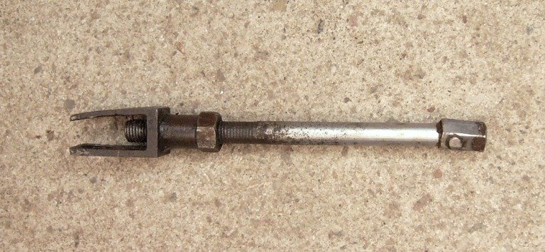
^ I was doubtful about the slave cylinder push-rod though, so I thought I'd ask you if this (once its battered forks are straightened) is correct with the square end on a pivot. It's not the same as shown in the parts book, but that tends to focus on the TR4 and perhaps this odd end was used on the 4A ? Btw., it works fine.
Oh yes, I also cleaned up the starter motor has which was pretty dusty and a little oily. .
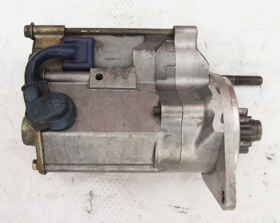
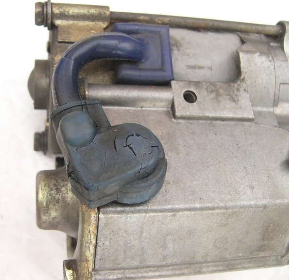
^ I only mention this as an advisory to other owners with a high-torque starter, as part of its cable insulation appears to be silicon, but the cover over the terminal is rubber. . .
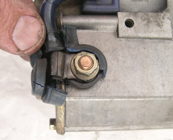
^ And that literally crumbled in my fingers. When fitted, this faces the engine block, so it's generally hidden from under-bonnet view. Beyond being salvaged., I cobbled together a cover in neoprene which I secured with a cable tie. I guess radiant heat from the exhaust down-pipes baked the rubber. Putting insulation on those pipe has move up my job list, as this heat damage probably hasn't done much for the starter motor or its gearbox lubrication either. I'll come back to checking and re-lubricating that anon.
In the meantime, I wanted to address the wiring that was loosely dangling over the gearbox, this of course being for the overdrive.
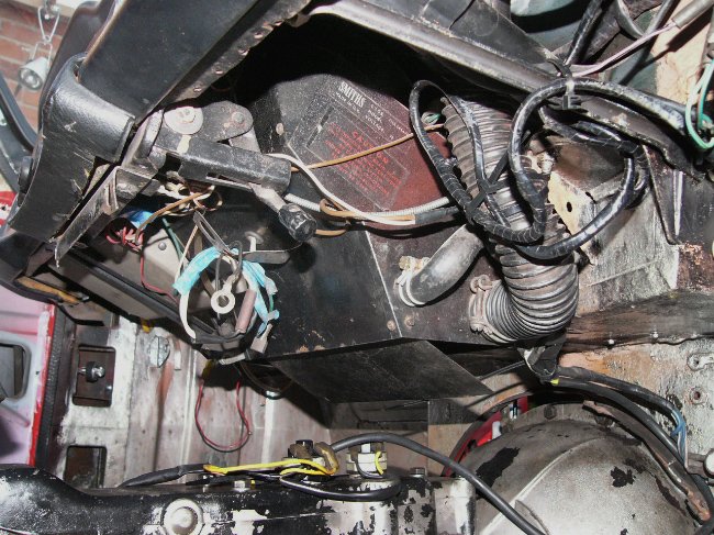
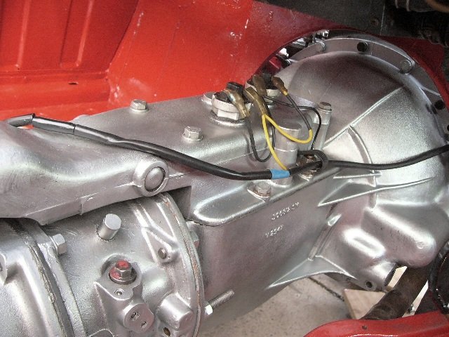
^ This is as it was, after the chassis change ..save my having taped over the solenoid's wiring connection and have better secured it with a cable tie to the switch. I've now (2nd photo) cut the wires to an appropriate length, replaced the bullet connection which was dangling away from its insulation (all new connections are soldered on), extended the outer protective sleeve, and secured the run of the cables with a clip from the top cover bolt ..which is no longer a bolt because I made a stud to go into that threaded hole ..for the earth lead. The wires will no longer go via grommet through the gearbox cover. Instead I drilled a new hole through the bulkhead just below where the throttle linkage comes out. That'll of course have a grommet.
You'll note in the first of these photos the dangles of wire alongside the heater duct (in the driver's footwell). Those are the other end of the overdrive's wiring, from the ammeter and ignition switch ..to/from its relay.
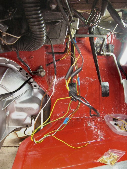
^ those same wires ..rudely exposed
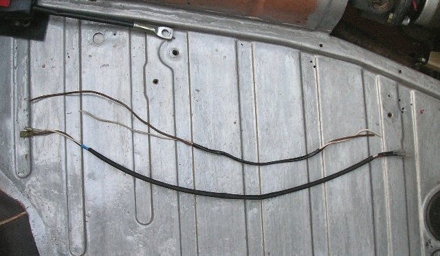
 And then (2nd photo) the wires from the ammeter and ignition switch to the relay. Bottom is the bit I'm reusing, that above is what I've cut out. In retrospect, having now refitted it, I would have made the 'reused' bit some 2" shorter. So literally, these wires are twice as long as they needed to be. Btw., left or right hand drive makes little difference, so I'm wondering if this overdrive's sub-loom was a universal item or came from another model of Triumph ?
While doing this I had the ammeter out and cleaned each connection and the bulb fitting, checked them for tightness, and liberally applied Vaseline before refitting. Likewise for each wiring connection I've touched. Again it takes quite a bit of time but I plan to go through every connection on the car to do the same. Better to do it now than to try and find a poor connection one night when it's peeing with rain.
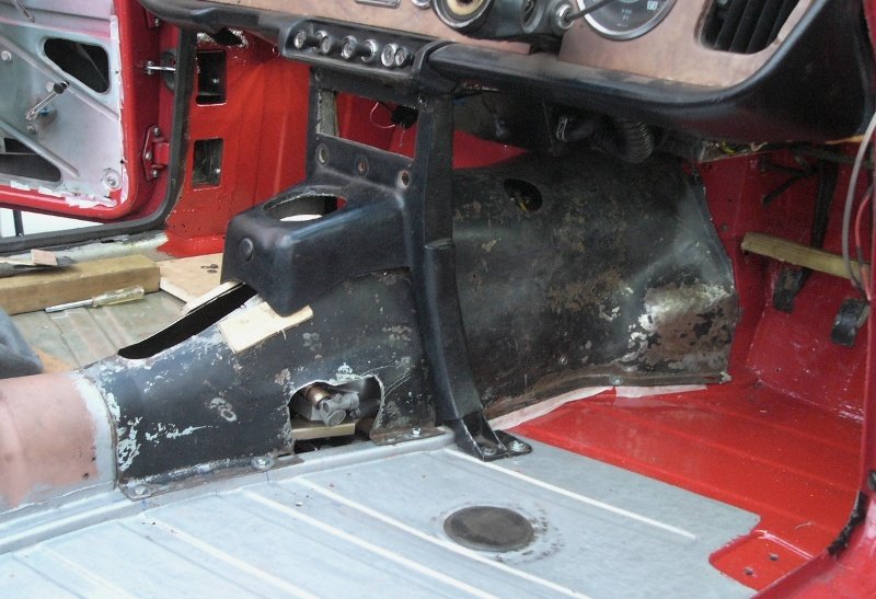
While under the dashboard, I took the opportunity to correct (..or at least improve) the dashboard / steering column stay. This is something Richard (RAHTR4) very kindly pointed out and advised me on, back in April. Thank you Richard, I knew I'd get around to doing it sometime. Funny how one or two other things sort of got in the way.

^ Richard had spotted, in a previous photo, that the stay (red Arrow) should be bolted via the bolt through the aluminium steering column clamp, and not to back of the dashboard, and at its bulkhead end.. should go the nut on the bracket (red circle). Instead it went to an home-positioned bolt, with half its head cut off, through the corner of the bulkhead panel, just under the clutch master cylinder. . .
He speculates that the bracket is from a LHD car. The one Katie (RHD cars) ought to have is not bent 90-degrees at the end and is shorter. For me working outside in 2 to 3 degrees temperatures this afternoon, it was quicker and easier to straighten the bracket's end ..but to keep it the same length. Oddly though, I did have to re-drill both ends from 1/4" to 5/16". Now (below) the one end is (just above the red arrow) ) bolted to the aluminium steering-column clamp, and I've taken the other end to the bolt (blue circle) at the rear end of the pedal-assembly pressing on the bulkhead, which I know to be strong. . .
That's all for tonight. Slow but steady(ish) progress.
Now that I've routed the wiring to overdrive I can get back to metal-bashing the gearbox cover again.
Bidding you a good evening,
Pete.
-
13 hours ago, Wagger said:
Hi Andy.
12v Heaters that plug into the accessory socket produce only 150 watts max. Hardly lukewarm. You need at least 500 watts. That is the limit of the Triumph alternator. There are 500 watt cabin heaters on the market for trucks etc.
If considered pertinent.. referring to the newly launched TR4 in 1961, Autocar wrote "A Smiths fresh-air heat with an equivalent of 2.5 kilowatts is a further option". This I believe was soon after introduction made standard equipment for many markets. I guess such a high output rate is required where icy cold air is being drawn in via the scuttle vent and within a few inches passing through a heat matrix it is expected to be toasty warm. Naturally a sports car with minimal insulation would soon loose heat as it drove along. I believe the 500w truck heaters are for when drivers are compelled to take a break for xx minutes, whereas those who sleep in their cabs would (for winter use) have something more substantial.
Pete.
-
11 hours ago, JohnD said:
there must be flow through the bearings. Pressure is what enables that flow. A totally blocked pump can register pressure in the absence of any flow at all! And a splash lubricated bearing has no pressure feeding it!
"there must be flow through the bearings" I never said otherwise, as far as I'm aware very few plain bearings are fitted with seals, and so flow is inevitable ..and indeed essential for replenishment with freshly filtered cooler oil, and for the splash lubrication / cooling of adjacent parts.
And to counter your counter, and to see you.. flow can be a dribble "in the absence any pressure at all "
 ..save that of gravity. Or flow may be circulation within a closed reservoir where even gravity is negligible
A hole which oil pours through would "register flow in the absence of any pressure at all!" ..but what's that got to do with the price of fish ? And splash lubrication does in fact have considerable inertia, at higher engine speeds, and therefore quite some pressure upon impact
..but surely such quibbling (what a lovely word !) is out of context with preceding posts regarding the effects of fitting an external oil feed to the rockers - no ?
-
1
-
-
^ Thank you David. It was pretty cold to work outside yesterday, but I was satisfied to take even that little step ..in the right direction.! Perhaps you are fortunate insomuch as your car doesn't need this sort of correction and preventative care ? I think it might be rather nice to be able to park the car up and know that it will be good to go in the springtime. I could instead be working on the boat !
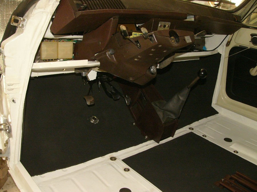
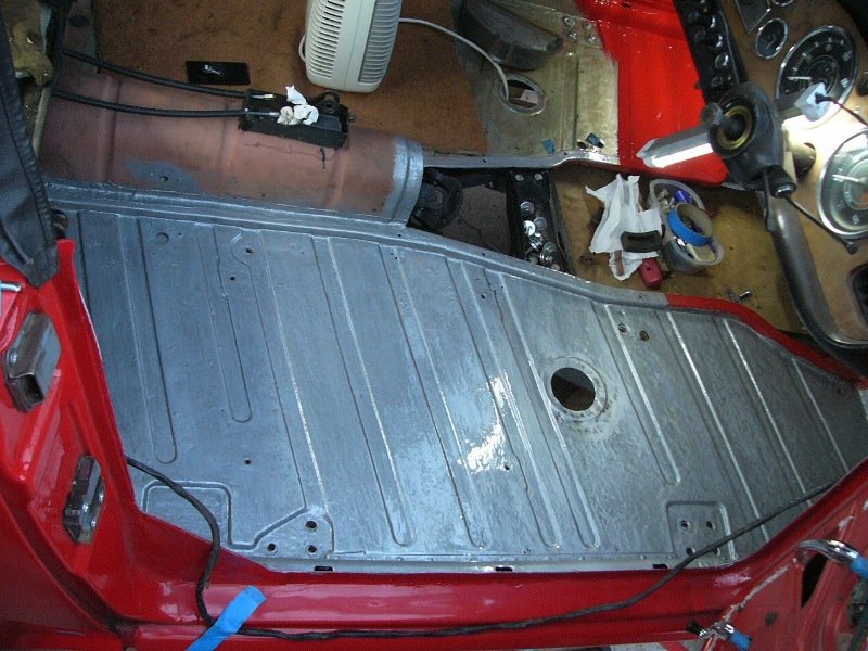
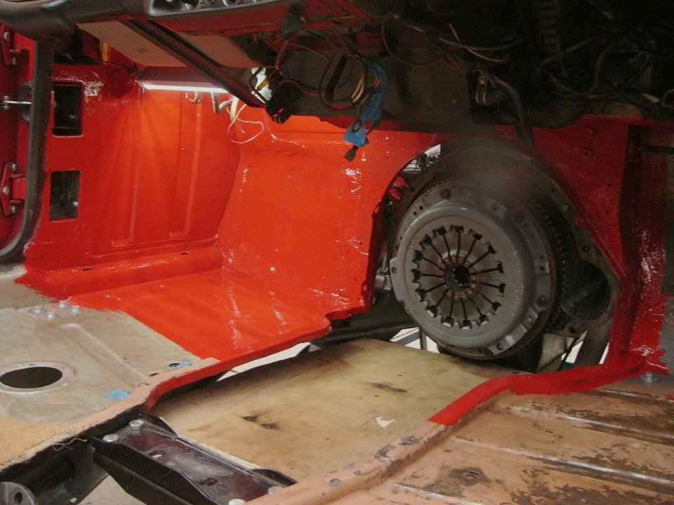
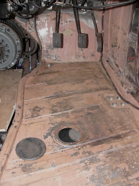
Today I painted the driver's-side footwell, bulkhead and side panel ..again while access was easier for me to climb inside and invert myself. My being right-handed makes this footwell all the more awkward to twist around to . . .
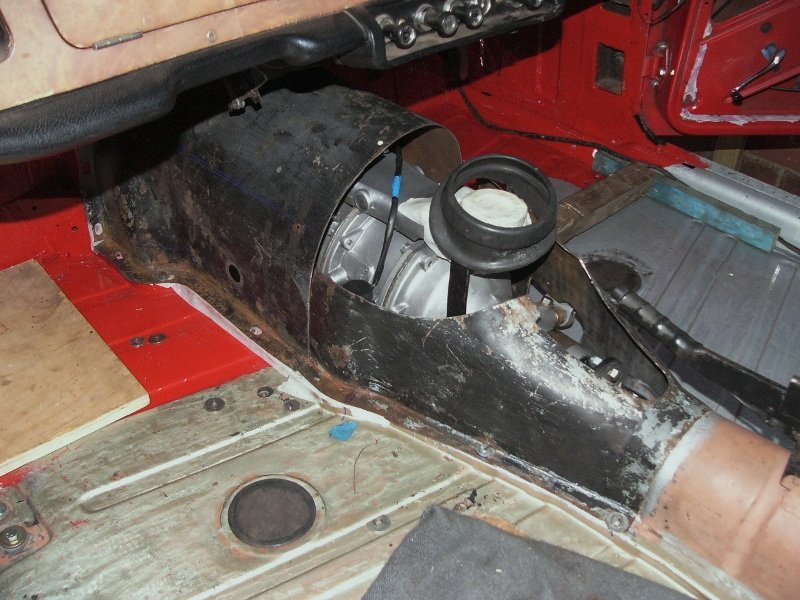
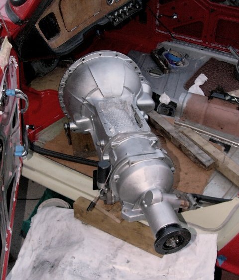
^ Painted to the same extent as the passenger side, again until I've dropped the gearbox back in and bashed its cover to shape.
And then back onto the gearbox . .
^ reassembly of the thrust-bearing & its fork mechanism, this time with a liberal application of grease in its bearings, and also cross wire-locking of both the standard pin and dowel.
Next job then . . .
^ reverse procedure of blocks to slide the gearbox on as when I removed it. Lifted over the door step first, with the overdrive resting on a 3/4" thick block resting on the sill's upstanding flange.
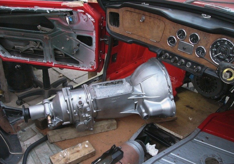
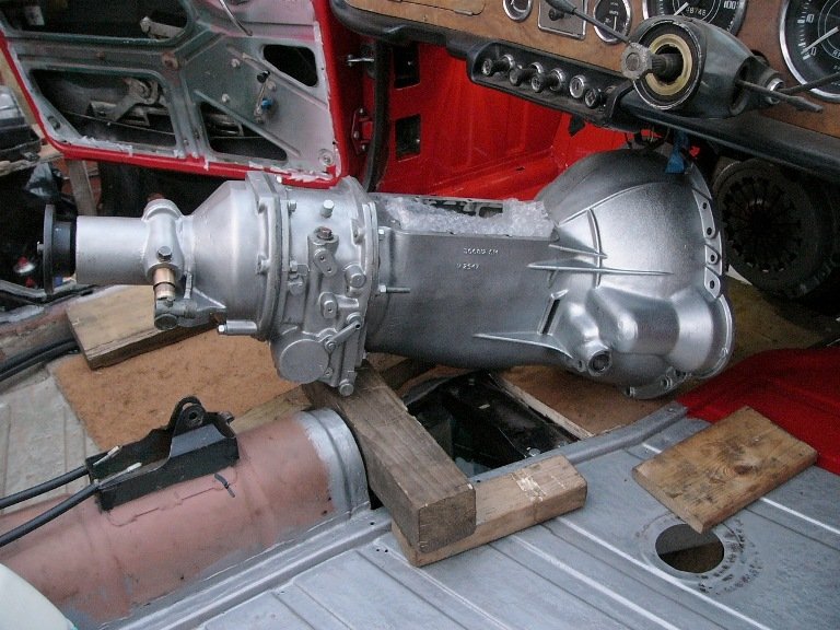
^ slid forward on the blocks as I lifted the back end around. The aforementioned 3/4" block was then moved from the sill to now protect the edge of the floor. From there the gearbox was slid forward onto the waiting board, still with jack and timber column support under it.
Blocks are positioned over the propshaft's forward UJ. Lifting the overdrive onto this bridge tilts the bellhousing under the car's heater. From there it is slid forward on the under-supported piece of plywood. Without drama, with lumber not strained, and all fingers and paintwork intact.
^ getting to this stage was fiddly, insomuch as the I made things difficult for myself.. because I had left the gearbox mount / bolt-on chassis cross-brace in place, and then also my extra-long (extended forward) T-shirt plate under the chassis prevented the propshaft from dropping lower (..had it just been an extra 1/4" lower that would have made life easier). Nevertheless with jiggling around the task was done, without loss of composure. From door sill to thus far took 40 minutes, on my own.
But then getting the input-shaft spline to engage with clutch ..so that the gearbox would push forward, proved a time consuming business. I was just about to give up for the evening ..to come back to it afresh in the morning, and gave things a last half-hearted shove, and lo n' behold it clicked forward. I cannot explain why it did so, as nothing had changed from my pushing n' shoving and twisting n' levering five minutes earlier.. but it kindly obliged and just slipped in.
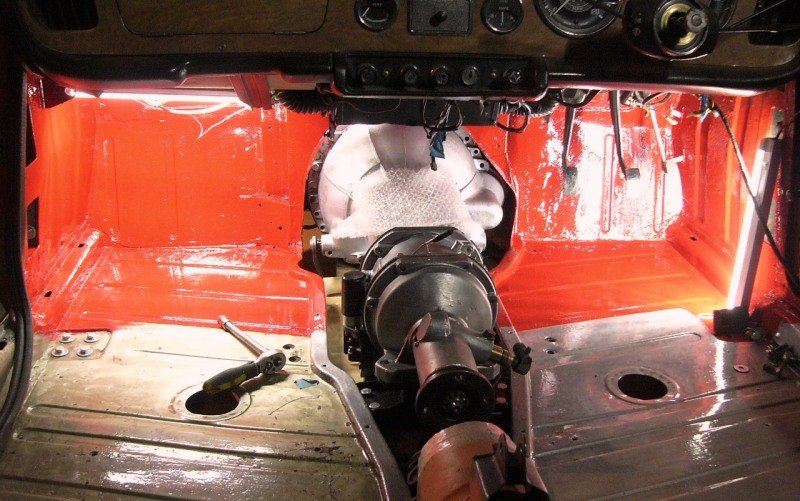
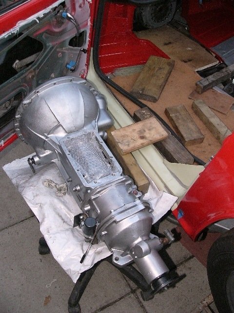
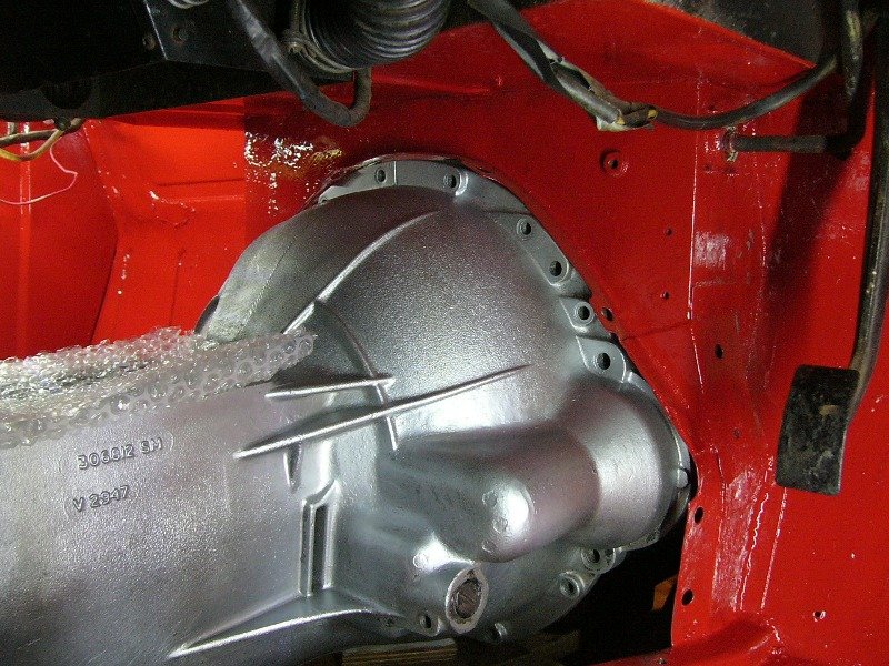
^ Gearbox back in ..still with paintwork intact and flanges straight. The gearbox mount is now back in place and I've a few bolts in the engine, and so it's nearly done. Tomorrow I hope to get things all bolted up, with the starter and clutch slave-cylinder back in place, and the gearbox top cover on again, so then I can move forward with reshaping its steel cover.
Progress., as well as footwell rust-protection and colour-correct prettiness ! Hopefully soon the gearbox will now be oil-leak free, and it'll all be brushed under the carpet !
Pete
-
2
-
-
If I might.. I note some confusion here because of the repeated reference to 'flow ' of oil, whereas the real issue in our older engines is one of oil 'pressure''. This is why our cars have an oil pressure warning light and often a gauge too ..and not a flow meter.
Plain bearings, including your big-end-shells, rely on the engine-oil being forced into the tiny tolerances between a loaded bearing and its journal. That pressure needs to be continuous, as this maintains the film-of-oil which the plain bearing rides on. Plain bearings, in effective, hydroplane on the oil.
The excessive capacity of the pump, is regulated within the lubrication system by its pressure-relief-valve (note again pressure ..not flow) and that accommodates, to a reasonable degree, wear in any of the plain bearings. As a bearing, or bearings, wears then the to-journal tolerances increase and whole system's pressure is lost, so the pressure-relief-valve operates to open less ..thereby maintaining the designed oil-pressure throughout the whole lubrication system.
Conversely ; ball, needle and roller bearings do not require their oil to be under any great pressure, in fact most are lubricated by the constancy of splash within the crankcases or gearbox. Often that splash is guided (but not under pressure) to dribble down on top of bearings. In other places there may be a machined scroll to proactively draw oil in to a plain bearing. Again these simply require a steady flow of oil.
Altogether a very low pressure lubrication system is very much more reliable ..because if one bearing is worn (or fails) then the others do not suffer oil starvation ..they are still getting splashed. And even when an engine is first started from cold - there is usually some oil sitting inbetween the rollers, even though oil pressure in the system is, at that instant, very low.
An oil pump is still required to draw the engine-oil through filters and then to take it to high points and very hot places within an engine (..to avoid all the oil draining down to the sump) and for cooling of those hot spots. And sometimes bearing surfaces are supplied with a jet of oil (..for example the camshaft lobes) but that again requires pressure, which the designers prefer to avoid. It's better then to have the camshaft lobes dipping into their own trough of oil. Other places require a jet of oil to cool a particular hot spot. But again this is a matter of much increased flow of oil over those places. In this design, the oil level is carefully monitored and low-on-oil warning lights are in place to advise the driver.
In practice, an engine's lubrication system is designed with both high pressure and low pressure / high flow. High pressure to the big end shells, and high flow to camshafts and with a lot of splash to other bearing and friction surfaces. If the oil pressure is contained within a few parts, such as the crankshaft, and its design avoids going through gasket faces ..then the engine is likely to be oil tight.
How does this relate to 50-year-old Triumph engines ? Well firstly it is necessary to know that the engine's plain bearing require pressure, and as importantly that the pressure is within a (restricted by design / semi-closed) lubrication system. Take away any part of that system and the pressure (within the whole lubrication circuit) will be reduced. That is unless the feed to those ares is otherwise restricted or blocked off.
Will the replaced mechanical parts need alternative lubrication ? ..yes if the oil path has been blocked off to retain pressure throughout the rest of the system, or else is not specifically directed at any new part needing lubrication, then an external oil route (restricted by bore size or jet, to preserve the oil pump's pressure) might used to provide the necessary constant-flow of lubricant to those parts. It is however a bold move to make such changes, unless for racing tenths-of-a-second-per-lap is the overriding criteria, as it risks greater damage to other parts. Arguably reliability wins races as much as a quickest time.
Hope that helps,
Pete
-
1
-
-
Happy Sunday.. where I like to wake a little later than usual, make myself a cup of coffee with toast & marmalade, and then go back to read in my still snugly-warm nest.. Luxury !
As a consequence I don't do much work on such days. In fact today I just did a couple of hours ..not because of any great urgency, but simply because I wanted to do this task while access was still easy, and again to allow the paint to dry before I continue playing around with the gearbox cover. . .
^ the first hour was more cleaning and wire brushing, solvent wipes, etc.,
^ second hour painting with POR-15, as I had done previously in the passenger side footwell.
Finished at 3:30, and that was it for today.. I bid you a good evening.
Pete
-
1
-
-
Thanks Mathew, I felt this paint covered very well indeed, it's just a single coat. I finished painting the floor soon after 3pm today (stormy, 5 to 6-degree c., 92 - 95% humidity, with blustery rain outside ..so very glad I now have the poly-tunnel). At ten past three I put a fan heater inside the closed car to warm it just a little ..not that the side windows or hood presently fit to seal it very well ! And of course there's no gearbox tunnel fitted so warmth would just drift away, and then the metal of the floor and bulkhead will be cold on their outside.
The fan was on its lowest fan speed and thermostat setting (so is mostly not on) and the new paint (on the floor) was dry but tacky to the touch two hours later when I stopped for the day. Freshly painted acrylic tends to feel tacky anyway. It feels much the same now at 9:50pm. I haven't reached further in to feel if the paint feels any harder higher up the bulkhead ..where there may have been a little more warmth.

Triumph engineers were fine fellows, insomuch as they placed a bunged hole in the floor of their cars to drop the heater's plug and lead through.. I'm inclined to think that was very considerate of them
Tomorrow's forecast is for 2 to 3-degrees c. temperatures, so I'll not expect it to harden very much in that.
Pete
-
1
-
-
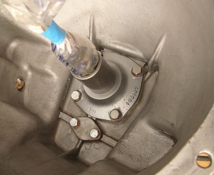
Slight change of plan today, I decided not to drop the gearbox back in yet. Last night, I noted in one of my photos that the other RHS gearbox-top-cover's threaded hole was also damaged. So, while the task is easy to do, I decided to fit a thread insert in there too ..not least because when I bought the car, its overdrive's earth lead was clamped under that bolt ..and so that thread may get a little more use than the others.
Therefore, in planning my day - I opted to repaint the gearbox cover's flange on the bulkhead, the underside of the battery shelf, and a section of the passenger's footwell.. Again while access is good. And then while that paint was drying.. I'd work on the gearbox again. . .
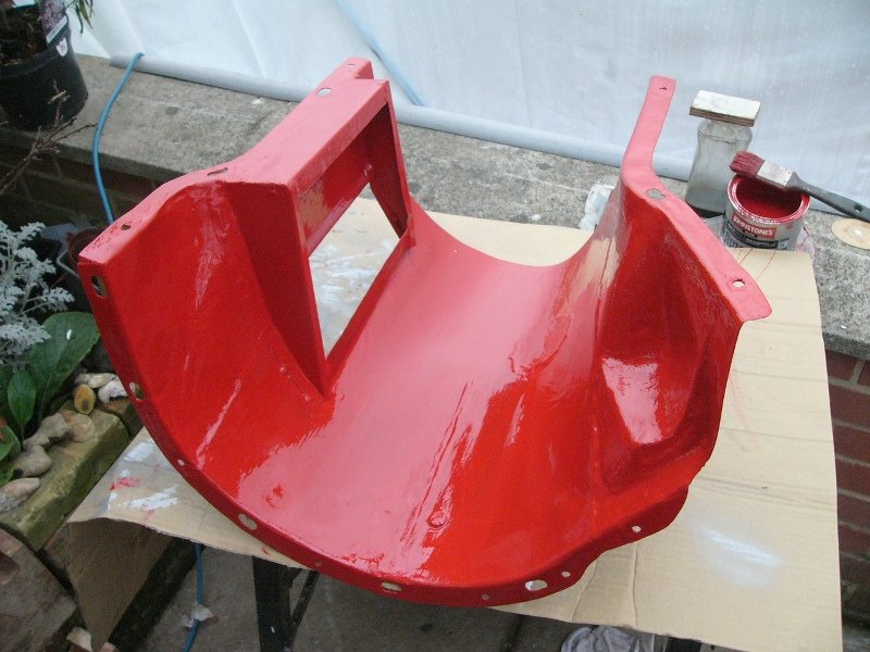
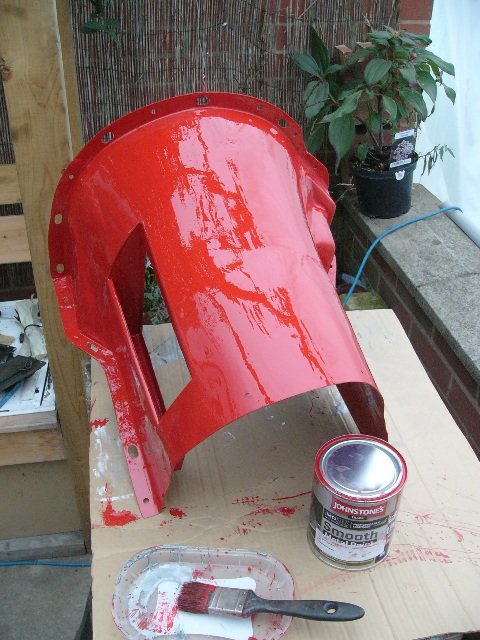
^ I'm very pleased with how this paint applied by brush and covered. It's thin enough to brush into the cracks of panel overlaps, but just about thick enough, even on this chilly day, to not run. It came from Johnstone's trade store and is their Smooth Metal Paint (Acrylic, so that I might thin it down with white spirits should I need it very thin / for wicking into joints). The colour is RAL3001 Signalrot (red) which is very close to this car (I took a piece in to be colour matched).
The rear half of the passenger footwell I'll repaint after the gearbox is slid back in and my bashing of the steel gearbox cover is done. The driver's footwell still needs a bit more cleaning up before I paint it with POR-15 (as I'd already done on the passenger side). It'll then get painted body colour whenever anon.
As intended, I then fitted another 5/16 UNC thread-insert into the top of the gearbox, before cleaning off the black paint and giving it a light blow-over with aerosol silver. . .
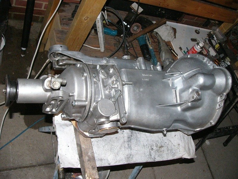
^ the (exchanged / reconditioned) overdrive was already bright n' shiny silver, but the gearbox and its bellhousing were patchy / flaky black paint with a smear of oil. Although I hope not to see it again very often, I'll now be able to more easily tell where any other oil leak may be coming from.
That's it from blustery wet Ipswich tonight. I bid you warmth in your home and a pleasant weekend.
Pete
-
1
-
-
In the meantime . . , aside from sometimes being idle, I'm taking the opportunity of clearer access to do a little more inside the car. . .
^ starting off with cleaning away the old gearbox-cover gasket, and straightening the (supposed) sealing flanges, which had been battered (..not by myself I might add). After all, if I hope for a reasonably pleasant car one day - then I really ought to avoid engine & transmission noise and fumes from simply wafting through the gaps.
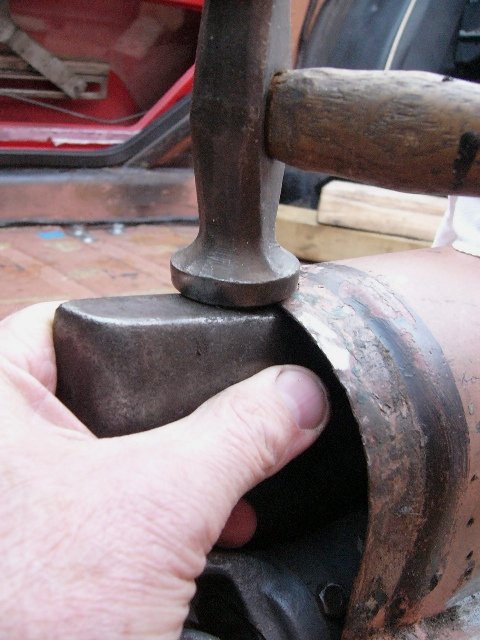
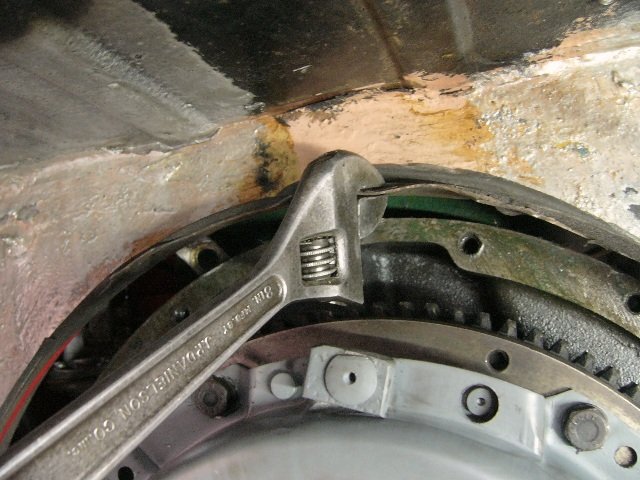
^ Use a hammer & dolly where I can, but in places where the access is limited then an adjustable spanner, closed down to the flange's metal thickness, provide an excellent lever for bending the metal back into shape. Note, the sealing / fastening flange for the cover, on the later cars, projects from the bulkhead. There are no fastening holes through the bulkhead itself.
^ I also took the opportunity (easier access) to start cleaning up the bulkhead and then the driver's floor of crud, surface rust and rock-hard carpet-felt goo.
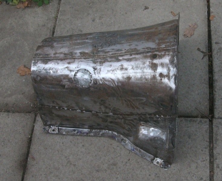
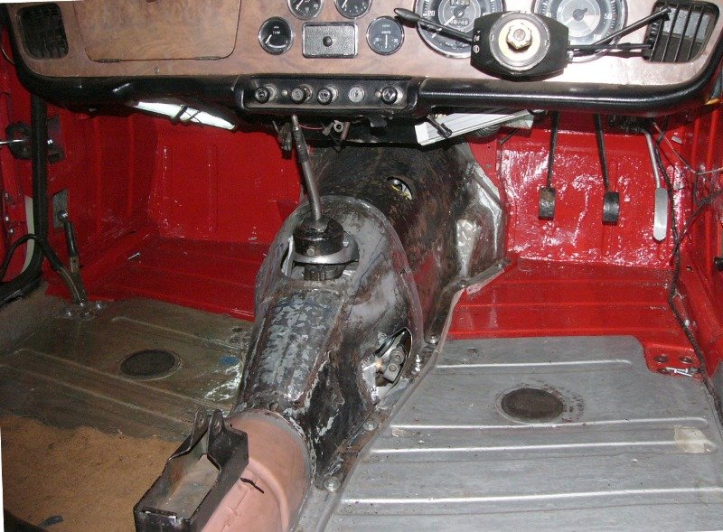
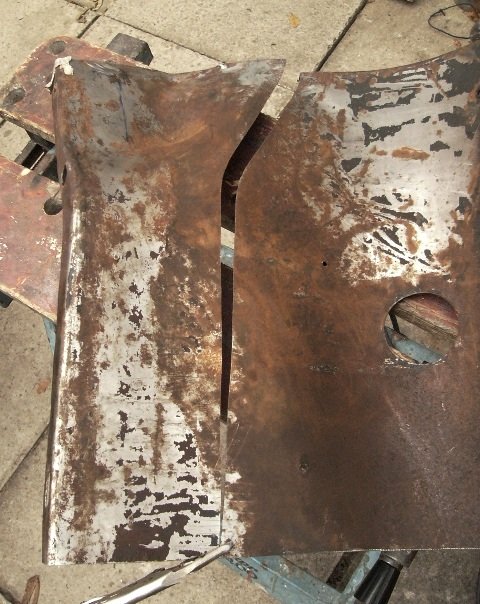
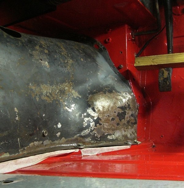
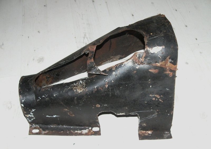
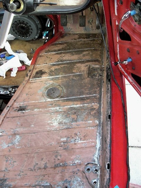
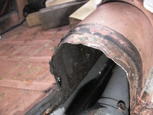
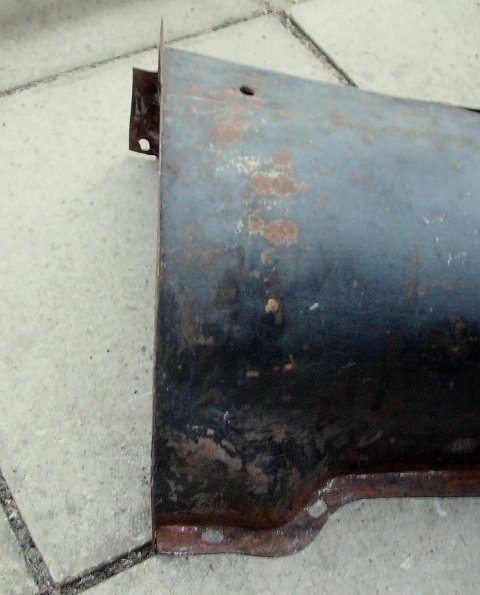
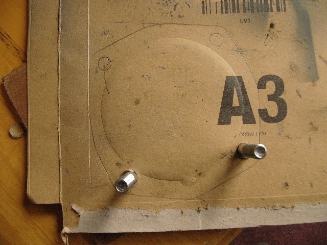
My keenness was to get back onto a task that I started half a year ago, and that was to replace the thin fibreglass gearbox-cover fitted, with a steel one from a TR3. . .
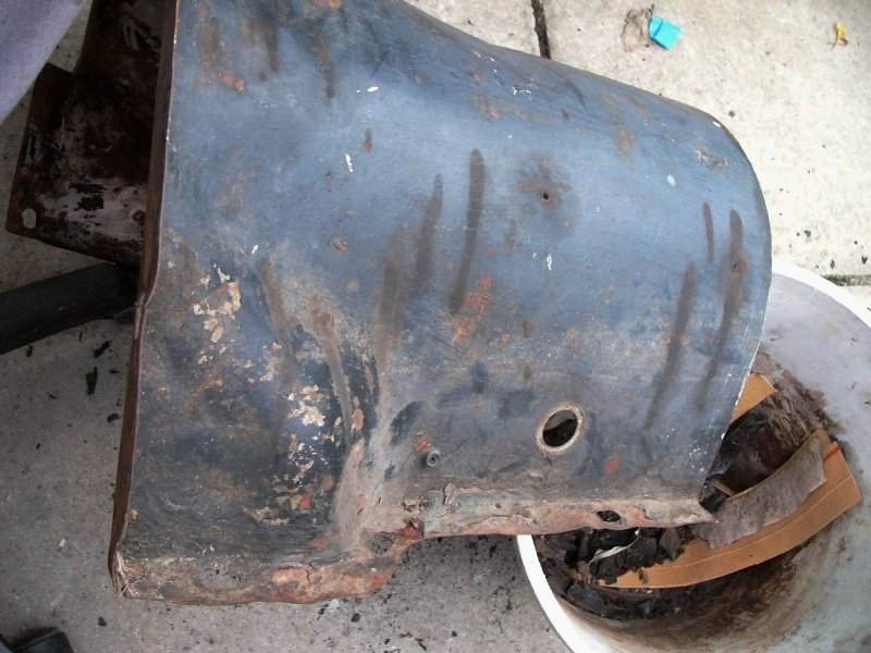
^ I'd already cut it in two, so that rear of the dashboard support / H-frame would be detachable without disturbing the forward (bulkhead / under dashboard) section. But I'd never got as far as cleaning it up nor to straighten its flanges. As you can see this cover's end flange (left hand side of photo), is designed to sit flat against the bulkhead of the side-screens cars. It is fastened through this to the bulkhead.
^ that's very much straighter, sitting flat on the floor and its forward (bulkhead) flange sitting nominally upright and square. But there was still some repairs to do where this 60+ year old cover had cracks through a couple of its slotted bolt holes.
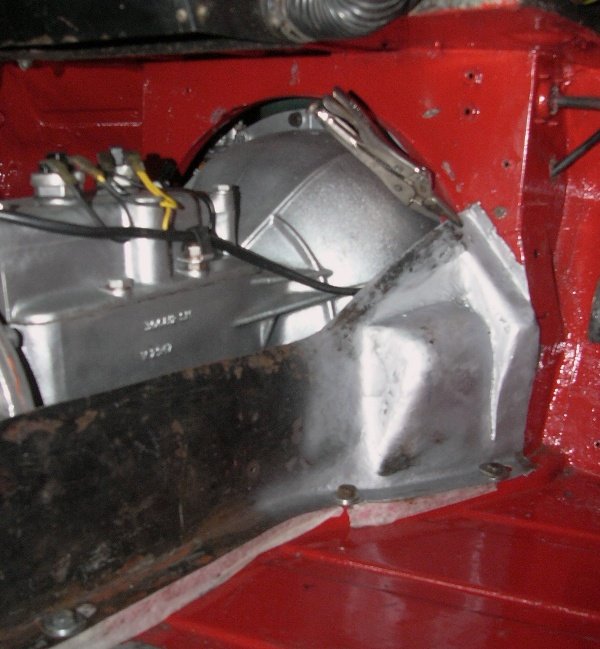
^ When fitted into the car this TR3 cover mostly fits the, 10-year later and massively revised body design of my TR4A. This is particularly amazing insomuch as the cover's fastening and seal flanges are different. Nevertheless five of the fastening bolts (1/4" UNF) around its bottom fitted without alteration (three on the RHS and two others on the LHS). This cover's height at the rear end (where I cut it off) is very much taller and wider than the TR4 type (which has to fit under the dashboard support / H-frame), but its fit to the body tub and along the floor edge is very convenient for its reuse.
^ From the inside you can see that the floor width is very good. NB, the TR4 floor-edge lacks a bolt hole in that front left hand , so the corner of the cover is not yet being pulled down fully). Otherwise, the cover's overall height around the front flange started off being about 8 - 10mm too tall. The steel cover has a hard corner shape on the LHS which needed a smoother curve. And a similar place on the RHS (at the top of the starter-motor's bulge) likewise needed a little easing and squaring to the TR4's sealing flange. Otherwise, the bulged shape around the starter motor was a little too rounded. . .
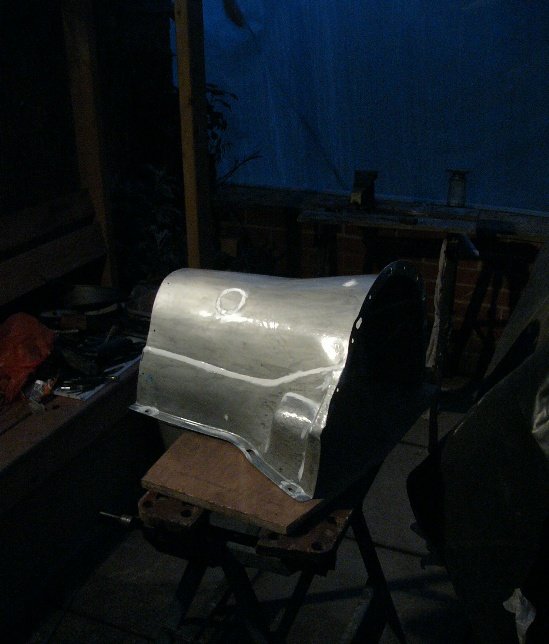
^ Although it took a while (..and an embarrassing show of bad temper when I ran out of welding wire ..just as the day's light was fading !) - the task of getting this cover to sit even better / flat against Katie's bulkhead, and down onto both side's floor edge, really wasn't that difficult a task. The width was already accurate, and the height at the front has now pulled down to about 6mm (1/4") too high. This is relative to the TR4's bulkhead sealing flange, but that really isn't too important to me as I can easily fill that with foam rubber.
all in all, good progress and a very pleasing fit (..all things considered) ..but then it was dark again and I couldn't see to continue.
If I get the gearbox back in the car in tomorrow, then that'll give me the height I can taper the cover down to towards its rear.
Pete.
-
1
-
-
Thank you Gentlemen for your continued support and good advice.
I've been otherwise busy these past couple of days, but this afternoon I refitted the front seal cover. As it was., I had already tapped and thread-inserted two of the four fastening holes with 3/8" UNC threads, while the other two remain as 5/16" UNC. . . . . .
^ of course, due care was needed to ensure that no coil wire end, nor bits of swarf, dropped into the input-shaft bearing or gear case. And, as before, the thread-inserts were Loctited in place and fitted just a little below the gasket face. Thankfully the length, the back-end of those through to the gear-case, were excellent. They are, I feel, now noticeably stronger than the original tapped threads.
Today I started off with a little shopping, to Suffolk Fasteners, Ipswich because I needed just two 3/8" UNC bolts and a couple of copper washers to fit those. Because I wanted a plain-shanked bolts for these ..I bought longer and cut them to length. I'd also cleaned things up, made a new gasket, and annealed the two copper washers I'll reuse. . .
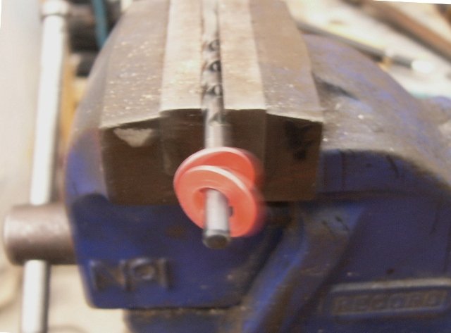
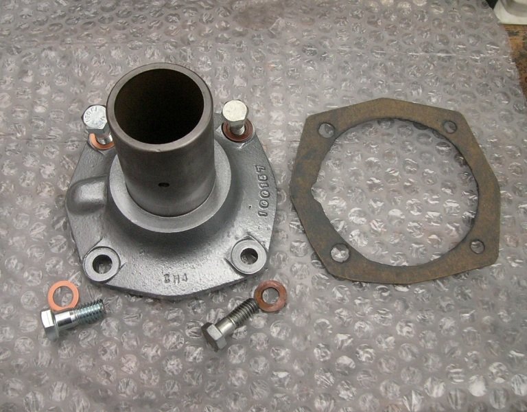
^ Parts all but ready. The inside of the cover's tube was water-proof greased to prevent surface rust. And the seal was given a liberal coating of synthetic lubricant containing Teflon. I used Wellseal on one side of the gasket (..which is first fitted around the bearing's retaining circlip) and a smear of grease on the other face.
^ another little minute job - done.
Hopefully tomorrow I get a chance to refit the thrust-bearing assembly and perhaps drop the gearbox back into the car.
Pete.
-
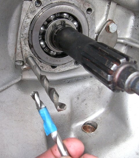
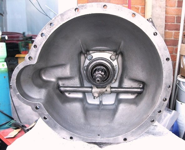
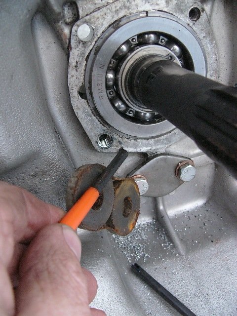
I guess someone made a mistake ..and pulled the wrong size drill out of their kit.. ^ The drill supplied in my UNC thread-insert kit, when tapping for a 3/8" insert, is in the hole, whereas that for the 5/16" UNC (the correct bolt size) is in my fingers. So someone over-drilled them, and then instead of finishing the job with oversized bolts, they simply used goo.
I might have sought sleeved inserts to fit into that over-sized hole, or else I was to go up in size to 3/8" UNC.. And that's what I've now done. Very awkward little task doing those two, so close to the input shaft, and within the bell housing, but I'm pleased with the way they've gone in. I guess I was very fortunate in preventing bits from dropping inside the gearbox, (using white grease on multiple layers of bubblewrap poked in, behind the holes, on the gearbox side) as subsequent flushing out with aerosol carb cleaner submitted no bits of swarf.
Copper washers were used, but I see in the workshop manual that wedglok bolts were originally specified.
Tomorrow I'll shop for a couple of bolts and copper washers to suit.
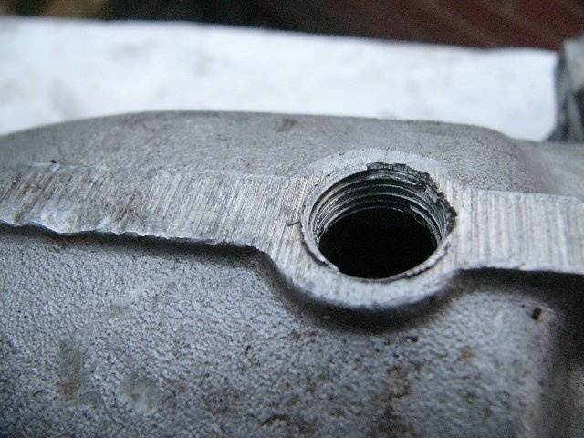
^ I'm equally as unimpressed with the drain plug hole, I'd guess that requires a special tapered tap ?
Pete.
-
1
-
")


 Someone was saying just the other night that they sealed off the gap between the bulkhead and the bellhousing on their Spitfire. Beforehand the gear-change lever got hot, thereafter it didn't. That seemed to be a rather neat and compact solution.
") . . .
. . .

 )
)
") Yes, in steel it will add a backbone the body tub. Getting things neat around the gear lever is awkward ..as is the compromise (particularly with the Triumph gearbox with its extended linkages and other bits poking out all over the place, plus the bulk of an O/D and its solenoid) in trying to make things tighter fitting (for the sake of interior space in a small car) and the smooth lines required for neatly fitting carpets over. Clearly the RX8 gearbox is much neater in that respect.
Yes, in steel it will add a backbone the body tub. Getting things neat around the gear lever is awkward ..as is the compromise (particularly with the Triumph gearbox with its extended linkages and other bits poking out all over the place, plus the bulk of an O/D and its solenoid) in trying to make things tighter fitting (for the sake of interior space in a small car) and the smooth lines required for neatly fitting carpets over. Clearly the RX8 gearbox is much neater in that respect.
 And then (2nd photo) the wires from the ammeter and ignition switch to the relay. Bottom is the bit I'm reusing, that above is what I've cut out. In retrospect, having now refitted it, I would have made the 'reused' bit some 2" shorter. So literally, these wires are twice as long as they needed to be. Btw., left or right hand drive makes little difference, so I'm wondering if this overdrive's sub-loom was a universal item or came from another model of Triumph ?


Daily drivers.
in Engine
Posted
I had a Volvo 145.. very good car with overdrive (switch on the gear-lever) and heated seats, but for the fact that it cornered like a narrow boat in a sea swell. I wonder.. if I were to drive one now whether I'd still think it a good car.?