

Bfg
-
Posts
1,168 -
Joined
-
Last visited
-
Days Won
44
Content Type
Profiles
Forums
Blogs
Gallery
Downloads
Store
Events
Everything posted by Bfg
-

Going to look at this. Any advice?
Bfg replied to Russ Rockett's topic in I thought I'd introduce myself
Pointy hammer would very much upset the owner of a genuine car don't ever do that to one of mine.! ..and it's not a solution to the modern way of fudging things, as I found out to my cost.. The sills on my Chrysler had been 'professionally' repaired (read 'patched over'), but come the MOT were found to have been just-very-occasionally been tacked in place and then seam sealer goo'ed along the seams ..for the most part. A magnet would have still clicked onto steel. Seam sealer seems to be the modern day equivalent to hiding c%%p under underseal. Sadly, I suspect some of that's recently happened on my Triumph too. In short, structural welding is now continuous, so if the panel joins do not appear welded then look carefully. Pete -
Back on the job., albeit slowly..well even more slowly than usual ! Yesterday, while the car was still unmoved, on the ground, and level I checked the front wheels were straight (tight cord again) and checked the ride height and camber of the front suspension. the check was both from the wheel centre to the arch and again under the chassis. I did this three times with no weight in the car, the 68kg in either seat, and then finally with the 104kg in the driver's seat only. Bottom line is that the LHS is 10mm high (as the rear LHS was previously) but otherwise the camber on either wheel was good to go. Sometime in the future I'll borrow a spring compressor and swap out the coli spring collars on the LHS but otherwise leave it as it is. Final job on the suspension then (..for the time being) was to lift the car back onto the ramps, load it up again with the bricks so that I might tighten the trailing-arm / poly-bush bolts up underneath. While at it to check the tightness of the half shafts and the flexi-brake pipes, etc.. Moving on. . , there were a number of jobs that needed addressing under the car. . . Firstly to grease the half shaft UJ's and the rear propshaft UJ. The first grease nipple was snapped off. I was very fortunate though insomuch as I managed to undo the broken off piece without dismantling again, by poking an Allen key in and turning it out with that. I swapped it out with one from the half-shaft I'd previously replaced. Although it (the grease nipple) had a slight kink in it - I presumed that was to provide a better angle for greasing. But no It had been bent.. and so as I pinched that one up, it too sheered off level with the surface. An Allen key didn't work on that one, but by chance I had a Torx key which did the job. With that removed I found one more grease nipple in the yet to be replaced half-shaft. Job done. Two pumps of grease and the gun was empty ! Hey ho., of five UJ's, I managed to grease the two closer-to-the-diff ones and the rear of the prop-shaft. One outer UJ had no provision for greasing (sealed to destruction) and the other had a grease nipple that was impossible to get at, unless I removed the half shaft again.! For the time being I've left it. I'll need to pull that half shaft out again anyway. ^ Why did it have to be the one tucked up behind the exhaust pipe ? ..just a two minute job huh ! ? ^ second grease nipple. On the right of these photo is the correct long straight type of nipple with small spanner flats ..borrowed from the spare half-shaft. Other jobs while down under . . . The brake pipe on one side would have been squashed under the bump stop, so that had to be moved aside a little. The brake and the fuel pipe were only loosely secured by a cable tie ..where they went into the rear of the tunnel, and the fuel pipe's run would have also chafed on the chassis. The cupronickel pipe was also buckled and I'm sure with vibration it would soon have cracked, so I'll want to replace it. In the meantime, they needed 'adjusting', securing and preventing from chattering against each other or the chassis. ^^ Note on the RHS of the second photo how the exhaust pipe is resting against the chassis gusset, and the way the underside T-shirt panel is buckled up in the middle. The brake and fuel pipes further forward were clipped but still loose enough to rattle against each other &/or the chassis. I've locally rubber sleeved and neoprene padded behind the pipes as necessary. The hard fuel pipe is joined at that corner with a short length of flexi rubber hose, with no ethanol-resistant markings on it and no pipe clips. I'll want to correct this sooner rather than later. And yes there is a drip of fluid from the slave cylinder, which I'd asked to be done. The LHS sill repair is not pretty ..more on that in a future post. I've taped over the holes in the side of the chassis rails (white PVC tape) to lessen water ingress. Those in the bottom are being left open for drainage. The chassis' underside T-shirt plate being pulled straight The cross-box silencer mounts were adjusted (re-done), to raise it up and better support one side (..one bracket now surplus) The exhaust bracket and clamp under the gearbox was 'adjusted' (..also a clamp now surplus ..the car is getting lighter by the hour !). A clamp was fitted at the front of the pipe (where it joins the double down-pipes) as that was missing. The second of those clamps is also missing and the old one is bent so I need to buy another. ^ when all was said and done the pipe and silence are now secure ..and there's 1/4" clearance at its tightest spot. You'll note in the top RH corner the brake pipe was very close to the exhaust. That too has been adjusted. While under I was also spotting the oil drips from the recently rebuilt gearbox (which was 99.5% oil tight beforehand).. ^ This does not please me. So., progress is being made, but its slow because of my own post-op limitations and the fact that working under a car on 8" ramps is itself a slow business. All so many details though will simply take some time to work through. And there are many more yet. Pending the weather, more next week, perhaps, Bidding you all a good weekend, Pete


- 1,015 replies
-
- 1
-

-
- tr4a
- restoration
- (and 3 more)
-
Thanks Mathew, I wonder how much change I might reasonably expect.. when the front suspension still needs tuning ?
-
I was a Design Engineer for many years, and although I might draw up something like this in an afternoon, there was a thousand and one things I was considering in the back of my mind ..from experience. Still, I take your point. Indeed the TR4A only used two of the three types of bracket, and although the original short springs and spacers were replaced by longer springs and no spacers, the options were still rather limited. But now we dealing with 50+year old chassis that may or may not have been rebuilt exactly to specification, so perhaps the need for a little post-assembly adjustment is understandable. Btw., I understand the 3-notch bracket was only introduced when the TR6 changed to stiffer springs to prevent that car from swatting under acceleration, and quite probably the effects of out of tune suspension was more noticeable still with wider wheels ..and in view of advancing standards during the 1970's. I guess very few of the racing chaps use TR4A's but I wonder if those racing a TR5 or TR6 set their own suspension or would they take it to a professional outfit.? "just brute force and ignorance" I think not. I'm guessing you get a feel for what moves which direction as you adjust things, and so do things pragmatically and probably very carefully. The problem I had with my previous 'classic' a Citroen Ami super was that the A-posts had been welded in the wrong place. Katie's not much better and the new sill is dismal. Although things can be fudged to lessen panel gap variations, there's a whole lot which simply cannot be done to achieve anything like a silk purse. Pete
-
A little more progress ..in the right direction After the weekend's exercise I was hurting. I think the sutures are breaking up, as they are supposed to do, and after so many sit-ups and twists working under the car (albeit on stands).. the wound itself is being pulled. Whatever the reason., it's very tender indeed. Bottom line is that I did nothing particularly physical yesterday, so today ..before the seasonal weather closes in I wanted to get Katie's rear suspension sorted. Today's plan was simply to swap out the coil spring collars on the rear LHS. If I get it right, it ought to lower the height the 10mm needed to true the car up, and also increase the negative tilt of the wheels. As said in my previous post ..the question is ; would these estimations be right. ? These are the spring collar options I have available to me at this time . . . ^ Top left is a rubber collar, as previously fitted, the spring sits on the rim whose thickness is about 1/4" (6mm) which soon squashes down to being 4 - 5mm thick. To the right of that is the poly-bush collar fitted by M&T, which as you can see has a larger overall diameter and a thinner inside brim. Its rim is 7-8mm thick and so probably soon squashes down to 5.5 - 6.5mm thick. Bottom right is one of the rubber collars previously fitted under this car's front suspension's coil spring. Larger in diameter and its rim is only 1/8" thick, but the impressions of having been used suggest that it doesn't squash down very much at all., let's say to 2mm. The advantage of the larger diameter rim is that it helps prevent this . . . ^ the collar seen squeezed out from under the spring ..when the spring load was reapplied. Clearly isn't going to do it job so it had to come out again. Perhaps it should have been assembled dry.? Anyhow it happened both top and bottom and so I used the new rubber collar (kindly supplied to me by M&T) at the top, in place of this previously used and slightly contorted one, and then I used a large diameter collar at the base, within the trailing arm's recess. ^ The front spring's collar is a larger diameter (inside out out) but just about squeezes into the rear coil spring, and then sits well in the trailing arm's socket. So with those swapped out, it was time to lower the car, load it back up and re-assess the car's ride height and rear wheel cambers. . . The results are perhaps a little better than hoped, with the LHS of the car dropping from 396.5 to 381mm, so 15.5mm. As before, the measurements were from the underside of the wheel-arch to the wheel-hub centre and so is independent of tyre size or pressures. That's more than I had previously planned (which was 10mm) and is a result of my using the very thin front spring collar in lieu of the original type rubber one. I'm happy with that ride height, as recorded as a static load with 150lb driver and passenger. I suspect it'll settle a little more with use ..which will then be even better for when I drive alone. The camber of that wheel has changed just a little more than predicted, because the ride height was changed more. So rather than -0.4 degrees it now measures as -0.44 degrees, which is a tid-bit of a bonus ..as my arbitrary target was -0.5 degrees. The RHS of the car, although its suspension was untouched, measured a drop in ride height of another 4mm. The only explanation that comes to mind is that the car is now sitting level rather than on a tilt. Whatever the reason, I'm glad for it. The ground clearance under the chassis side rails (one side to the other) is within 1/16", with either side now sitting between 5-11/16" and 5-3/4". I'm very happy with that too. Its negative camber has increased because of the car's tilt being corrected, and now measured as -0.94 degrees ..which is more than my target. Next I altered the load condition once again, to simulate no passenger and with me (105kg) driving. Without the weight in that side, the LHS rose by 11mm but the reversed tilt of the car changed its camber to be -0.51 degrees. I like that. With the additional weight in the driver's seat, the RHS of the car dropped by 5mm and the camber (because of the car's tilt) swung back to -0.58 degrees. I like that too ..but for the implication that I ought to loose some weight ! That's it., the rear suspension is set up to where I wanted it for solo driving. The rear's ride height is now acceptable (..the body mounts are new & thick so the body is a tad high on the chassis but I'll live with that).. and the car is even from one side to the other. You may recall before the chassis swap Katie was riding particularly low on the RHS. Most importantly for handling, the rear wheel camber on either side is so close to my target figure that... I'll not write more about it .! I just need to crawl under the car once again to tighten all the bolts up in this load condition. Then it'll be.. Job done.! And if i can do it without specialist tools, then so can you Bidding you a good evening, Pete.


- 1,015 replies
-
- 2
-
-
- tr4a
- restoration
- (and 3 more)
-
Following on with my adjustments of Katie's rear suspension, from 20th September ..and it's now 11th October - phew but that's how life goes. Ten days after the op I was down under again. I'm sure the NHS discharge sheet says something about 'light exercise' including (but not limited to) getting down and back-up again from the floor (x100 times), twisting, crawling and reaching to undo rather tight half-shaft bolts, pumping up n' down on the trolley jack handle, and of course moving 136kg of bricks into and out of the car. Still, I'm now having an easier time than Mathew ..who continues to battle on with his ailments. Keep up the good work matey, see you soon. During my convalescence I was struggling to fathom out why suspension adjustments on the car didn't match the figures in Buckeye Triumph reports. So I looked again and picked up a few errors, then remodeled the Trailing-arm geometry for a second time in 3d (Rhino computer program). Possibly I'll pull together a fuller report for the benefit of other TR owners, but here are a few tidbits . . . ^ this is one of the 3d computer models I generated and manipulated to try and better assess what was happening to ride height & wheel camber when the trailing-arm brackets are swapped around. I was working on and so modeled the rear RHS trailing arm of my TR4A. And so as if viewed from the back of the car, the wheel can be identified in the bottom RHS of this screen capture. The row of lines at its base are a visual guide to wheel height (best seen from the side view) which of course is a direct representation of ride height. The black line up from those is a vertical datum, against which I measured the wheel's camber. The wheel and the green lines (which represent the trailing arm) were joined together as a block, so they might be pivoted as an assembly around the polybushes, in their brackets bolted to the chassis. The row of blue lines near the middle of this image represent the various position / options offered by the selection of three types of trailing-arm bracket. The red line seen running diagonally though those is axis of the polybushes,, around which the arm and wheel-hub, and the therefore wheel itself is swiveled (3d_rotate in Rhino ). The cyan coloured circle represents the bottom of the coil spring. The coil spring, with its vibration insulation collars, have a predetermined length ..for any particular load condition. The TR4A manual suggests setting the suspension up with 150lb (68kg) of weight in either seat. The top position of this spring length is fixed (within the cup of the bridge on the chassis). In regard to swapping from one trailing-arm bracket to another.. the height of the polybush axis moves higher or lower relative to the chassis rail. So then., if the height of the polybushes is moved down (when a different trailing-arm bracket is used) ..and the road-spring has a predetermined length, then the back-end of the trailing arm ..complete with wheel-bearing hub and wheel, go up. In short, the change in height of the polybush seesaws around the bottom of the road spring. It's position was estimated from the dimension given in the Buckeye report. The rough dimensions were 10.5" to the spring and 19" to the hub, but I feel they were incorrect in calculating the effect of height rotation based on those dimensions " If you draw a couple of sketches you'll see that the car height changes 10.5"/19" or 55% of the change in bush axis height " How's that.? When I draw a 19" long seesaw with its pivot at 10.5", and then raise the polybush end by 1" ..the other end goes down by 0.81". I suspect they were also very slightly inaccurate in assuming the axis of the wheel hub was in the 2-dimensional same plane. In practice the polybushes are quite a bit lower on chassis than height of the centre of the wheel (..as you can see in the illustration above I've drawn the height difference into my 3d model). Conversely the bottom of the spring is down at the chassis level. I wonder too, if measuring to the centre of the road-spring within the trailing arm is correct. I'm thinking a drop in polybush height rotates around the front edge of the bottom coil of the road spring. That may not seem like much but again this effects the ratio of change, so instead of 10.5" the dimension I used is 8-3/4". Referring back to the sketch of a 19" long seesaw, but now with its pivot at 8-3/4". Raising the polybush end by 1" ..and the other end goes down by 1.17" ..compared to their 55% (0.55") that's a over double the effective difference. Not only does this effect the ride height, but any suspension travel also changes the angle of wheel camber. Moving on. . . As you can see in the illustration, I've played with the model and listed the effects of changing from one bracket to another. NB. this computer model's adjustment is completely manual, and therefore subject to minor error. I'll come back to those figures in a short while, but firstly let's quickly review the trailing-arm (bush mounting) brackets . . . ^ this screen capture of my Autocad drawing shows (on the LHS) ; a plan, side and end view of a bracket. It shows the two mounting bolts to the chassis rail and the one through the polybush (rubber was original and so may be substituted). Through the side view you can just about make out the yellow centre-line, equidistant from the two bolts. And from this a dimension of 9.35mm up to the centre axis of the polybush. With that offset, this bracket is a 2-notch type. Turned over, on the two bolts, and the offset to the bush would of course be down rather than up. Not illustrated, but the 1-notch type of bracket has a 3.2mm offset from the yellow centre-line, and the 3-notch type of bracket has a 15.8mm offset. These figures are very slightly different to those in the Buckeye report because I've assumed they were designed & made to imperial dimensions.. with offset of ; 3/8", 1/8" and 5/8" respectively. The two trailing-arm brackets are centred at 13-5/8" apart when mounted onto the chassis (illustrated across the top and bottom of the drawing), and the ends of each blue dashed line (each 1/4" apart), represent the bush centre with each possible bracket position (viewed square-on to the chassis rail). The brackets illustrated represent a 2-notch and a 1-notch. Drawn to scale the height of the polybush bolt is very apparent, with the ' OUTSIDE ' bracket (left) being higher than the INSIDE bracket. It looks a lot but the angle between them (seen as the green dashed line) is only 2.08-degrees from the horizontal. However in detail, the polybush (or rubber) is expected to do this . . . ^ I wasn't happy with that, because it's like hanging a door on hinges which aren't in line, so.. ^^ on my own car, I've slotted one hole (in either bracket) sideways by a millimetre. The other hole(s) were untouched, and so the bracket's position on the chassis is unchanged, but the slotted hole allows the brackets to tilt so the polybush bolt and pivot axis are in line (ie., the whole bracket now sits at that 2.08-degree angle rather than torturing the bush). Anyway back to the figures I took. . . The TR4A with standard ride height, wheels, tyres, etc., was designed with a 2-notch bracket (notches Up) on the OUTSIDE and a 1-notch bracket (notch Up) on the inside. Then, at the correct ride height / loaded according to the workshop manual's specification (a nominal 150lb / 68kg on each seat), the rear wheel's camber would be zero, +/- half a degree. ie., they would be vertical - That's easy. And so that's how I set my computer's 3d model up. I modeled what I had on my car ; with the 2u-1u brackets, and its ride height being a little high, and its +0.73 degree wheel camber ..and then rotated the 3d 'trailing arm, hub & wheel assembly' around the polybush axis until the wheel camber measured zero. This was the equivalent of lowering the suspension by almost 12mm. This gave me the as-designed Standard rear suspension geometry. Then I systematically changed the type of bracket and their orientation (up or down), and for each I rotated the back end of the trailing arm back to where it touched the bottom of the road-spring (that having a predetermined length for that load condition), and measured the consequential height and camber of the wheel. The results were as follows . . . Brackets Height Camber (degrees) ; 3d-1d +6.59 +0.83 2u-1u 0.00 mm 0.0 1d-2d - 6.53 - 0.83 1u-3u - 12.50 - 1.63 Then tilt the bushes one notch and repeat ; Brackets Height Camber 3d-2u + 11.58 + 2.30 2u-1d + 5.00 + 1.47 1d-1u - 1.50 + 0.64 1u-2d - 7.93 - 0.19 2d-3u - 14.29 - 1.02 The first thing you'll notice is that, compared with the Buckeye report's table (submitted in a previous post), there are very few results. This is because reversing the brackets (inside to outside) so the trailing-arm bush would be lower on the outside bracket, isn't (for all practical purposes) likely to happen. If that extent of camber change ..to positive, is required, then it very much points to the chassis having collapsed in the middle. Similarly, if the same type of bracket is used both on the inside as outside ..whereby the bush axis would be parallel with the (supposedly horizontal) chassis rail. Only if a car is custom-lowered might those bracket configurations be required, and those are outside the remit of my investigation. The second thing you'll note is that I've presented the figures in two parts. The first four bracket configurations are simply moving the axis up or down, from standard, with the 2.08 degree angle of the polybush axis (relative to the chassis) remaining the same. The second set has tilted the bushes one notch (one degree greater angle) and then again moving that polybush axis up and down. For those who prefer here is a graph representation of the above figures . . . ^ Mostly speaks for itself, but the grey grid lines are from the first four bracket configurations and those with the green grid lines are from the last five. Those with the blue lines are the datum (standard TR4A set up) from which the others are measured. This means that the figures are relative (..albeit hand measured). So anyone adjusting their own car's suspension (whether TR4A, TR5 or TR6, or Triumph 2000) has to firstly accurately establish what they have, and then to adjust from that datum. The graph is easy enough to read insomuch as if you were to change from the standard (blue grid lines) bracket configuration of 2u-1u (outside bracket - inside bracket) to 2d-3u (found as the lowest red dot in the bottom left hand corner), then you might expect a 14+mm (14.29mm) drop in ride height and the wheel camber angle would tilt towards the negative by 1.02 degrees. This is what I did on my car (this last weekend) and the car did indeed drop in height and the RHS rear wheel's camber is now -0.30 degrees. Starting off from +0.73 minus 1.02 = -0.29 degrees ..so what I predicted was achieved (+/- 0.01 degree). That is on the RHS of the car. The LHS of my car is sitting 10mm higher, and so has a tad little less camber (it is now negative though). I'll (hopefully this week) correct this by swapping the spring collars out for thinner ones.. The ride height will drop and so the wheels camber will tilt a little more to the negative. ^ after swapping out the trailing-arm brackets, I'm checking the camber angle of the LHS rear wheel. I have each seat loaded with approx 64kg of night storage heater bricks, and the ground has been leveled (with a piece of 1/4" plywood under the RHS rear wheel). The car was lowered, loaded up and bounced upon, and moved forward onto plastic bags (which are a poor man's slipper plate, to allow the tyres to slip sideways and otherwise settle where they will). The car was bounced upon again to allow it to settle without the tyre's wanting to scrub sideways. The spirit level is vertical and aligned to a mark on the wheel-arch (so the same place is measured from each time) and then the dimensions to the top and bottom of the wheel rim was recorded (in this instance just 1mm difference between top and bottom). With 395mm height between rim measurements, the figures were used in a drawing (on the computer) for it to tell me the camber angle was -0.15 degrees. Hey ho., getting really close to what I want. This (above) is the side which is 10mm higher, and although I'll lowering it ..it already looks much better than as the car was sitting when I collected it after the chassis swap. It then had both a higher ride height and the wheel had positive camber ..measured as 5mm difference between top and bottom (wheel rim to the spirit level) = +0.73 degrees). How much difference will lowering make ? Well, while I had the computer model open I checked. Again using the same 2u-1u brackets as a Standard setting to assess these things from, I rotated the trailing arm around the polybush axis to simulate a change in ride height (whether caused by car load, cornering load, or alternative spring length) and here's the figures . . . Brackets R/Height Camber 2u-1u +30mm + 1.94 2u-1u +20mm + 1.29 2u-1u +10mm + 0.65 2u-1u 0.00 0.00 2u-1u -10mm - 0.64 2u-1u -20mm - 1.33 2u-1u -30mm - 1.94 degrees Those same figures present in graph format . . . ^ Again self explanatory. The figures (red dots) are again from the hand manipulated computer model and were close enough to set a line through (the -20mm figure along the bottom was adjusted by 0.03 deg to fall into line). From this I can see that if I drop the suspension on the rear LHS of the car by 10mm, it will have a -0.65 degree effect on that wheel's camber. However when doing this I also have to factor-in that the tilt of the car (over a 48-1/2" track of the rear axle) is about 0.4 degrees, and so the net result will be closer to -0.25 degree. But then the camber on the RHS corner will also alter. With this information I can get it right (..with a fraction of the trial and error of spanner work under the car), or I can determine how much effort is it worth versus whether I'll actually notice the finer aspects of its adjustment. Most likely I'll drive the car a little, let the springs settle into their poly-bush collars and reassess things later on. Out of interest though . . . I was interested to assess the car itself when removing the passenger, and adding more weight into the driver's seat. I'm 105kg so I loaded 13 x8kg bricks into the driver seat and all off the passengers.. The ride height (hub centre to wheel arch) on the passenger side went up by just 6.5mm, and the camber changed by +0.15 degree ..taking that side to zero camber. The ride height (hub centre to wheel arch) on the drivers side went down by just 2mm, and its camber changed by -0.29 degree ..also taking that side to zero camber. Interesting ! These are of course static loads and the camber would change when the suspension is loaded ..around corners. Have a good evening, Pete


-
sacrificial anodes to the god Ferrous. Did you know that a particularly famous architect designed ..and had built, a ship clad in copper. Apparently when launched in seawater the electrolysis was something to behold. Conversely, as if there wasn't enough salt at sea.. salt blocks are used to scrub the timber of decks, and are also added to water in the bilges of vessels built in timber. - - - Back on the subject of Triumph suspension. Mathew kindly shared a few images of the Triumph 2000's IRS. As the TR's IRS was derived from this it makes an interesting comparison . . . ^ Triumph 2000 IRS. The sub-frame assembly onto a monocoque body shell is pretty neat. Also of note is the telescopic damper mounted directly to the body tub, whereas the TR uses lever arm dampers which are of course assembled onto the chassis. I was particularly interested to see the angle of those sub-frames ..and their trailing-arm bush axis, relative to the axle's axis ..which from the photo appear to be 40+ degrees rather than the 32 degrees of the TR's. I presume the 2000 required more camber change (to negative) to counter the saloon car's tendency to roll. The 2000's inner and outer trailing arm bush brackets are different, ..as they are for the TR's, so I guess the selection of those is likewise used to set the saloon's rear wheel camber. For comparison, my own TR4A chassis mounted IRS (below) . . . I wonder how many, if any, components are interchangeable between the different models. ? Pete


- 1,015 replies
-
- 1
-
-
- tr4a
- restoration
- (and 3 more)
-
We use Stainless steel quite a lot in the marine industry, often taking some pretty impressive structural loads. Mind you we also have aluminium masts, copper wiring, lead keels and bronze tubes through the hull.. so what might that say about us ! ? ..and that's aside from the timber of the bulkheads and in hull framing, engine beds etc., and then foam or balsa wood for our structural laminate cores, and then sail cloth to propel the vessel.! ..the motor industry is just so die-in-the-wool using iron and steel all the time.
- 1,015 replies
-
- 1
-

-
- tr4a
- restoration
- (and 3 more)
-
^ Those are amazingly skinny brackets, and the bolt thread looks coarse ..I too would share your concern. The brackets on the Tr4A - Tr6 are made from 3/16" (4mm) plate so possibly less of a concern. Pete
-
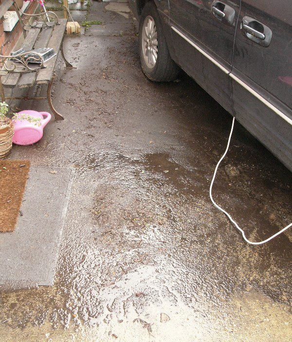
The bolts through the bush and bracket would need to have a 3" long shank plus its threaded length. Possibly more readily available as 4" bolts that can be cut shorter to suit the tight fit between the bracket and the rear chassis rail. What Colin says is correct and good practice but as Peter implies ; probably unnecessary ..as when the whole assembly is bolted up tight (done while the suspension is loaded of course) then the ends of the crush tub should not move relative to the bracket and therefore neither the bracket nor the bolt's thread would wear. Thank you for your best health wishes and cautions. The operation was for "a large left inguinal hernia" which is possibly why I had a large open incision across the left groin, and then a rather tender four to five inches of Frankenstein-like sutures and a whole lot of deep bruising where no one wants it. Naturally I would have preferred key-hole surgery, but hey.. they didn't wake me up to ask my opinion.! Had I known beforehand the effects of general anesthetic on my system, then most likely I would have taken stool-softener medicine before and immediately after the op ..because five days worth of blockage pressing from within was, I feel, unnecessary and avoidable pain, distress and discomfort (..lots of each). The sister of a close friend had the same side effects after having general anesthetic., so I'm not alone. Indeed the post-op literature makes a big deal about avoiding constipation. But by then it is too late, and thereafter eating only gruel and soft fruit wasn't enough to correct the issue. Anyone facing surgery might want to heed this warning, but also to seek their doctor's advice, so as to avoid any conflict in medicine. Anyhow, once unblocked, I took to light exercise, as highly recommended ..and managing to walk about 3/4 mile (round trip) to a local shop on the Saturday (the op was late on Tuesday afternoon), and then four or five miles on the Sunday, another three or four miles on Monday ..by which time I felt I was hurting myself. So Tuesday I had a day of rest. In the meantime (Monday night, I think) we had a 3 - 4" flood on the patio where my TR is up on ramps. Once that had subsided, there was of course a whole lot of crud to sweep up and wash out . . ^ my 'light exercise' for today was to clean up this S%%t. Perhaps it doesn't look too bad in the photos but just from this space and under where the Chrysler is parked I swept and shoveled up the best part of a wheelbarrow load of crud. I'm now aching (both front and back !) more than would have liked ..but at least now the ground under the car has half-a-chance to dry out. Job done for today, I'm going to take it easy now. Wishing you a peaceful evening. Cheers, Pete.


-
Good point Gully, I was struggling to understand why the measured change in ride height and camber was not closer to that predicted in the Buckeye-Triumph reports. Dwelling on the issue and work the car came to a halt with my having to prepare for having a minor operation. I live alone, so things like grocery shopping and house cleaning, bedding, car insurance and other bills, as well as positioning of furniture as zimmer-frame like aides to getting up n’ down etc., all had to be done / dealt with in advance of my being laid up thereafter. Then last Tuesday I was surprised to wake up from having open-surgery rather than key-hole as expected. Anyway, right now I'm on the mend again, but off physical bending, stretching & lifting exertions, including jacking up the car, crawling under it, undoing and lifting off a wheel, &/or reaching and struggling to loosen half-shaft and trailing-arm bolts. I hope to get back on with it soon but in the meantime, when able to concentrate, I've been looking again at the Buckeye-Triumph reports. I've found a number of errors in their figures. Their author’s thinking of what happens when adjustments are made has been really helpful, but in practice their measurements were a little off. Tbh., not enough in themselves to make a significant difference but possibly enough to confuse the issue ..of why actual adjustments don't result according to prediction. However, your point of my adjusting just one side and then re-measuring the effects ..on car now leaning, is inspired. Thank you. TBh., I really didn't think it would make much difference over the full width of the car (the axle's track dimension), but I've just checked.. and just 10mm lower suspension on one side, on the TR4's track width of 48.5" (1233mm), equates to the car leaning by almost half a degree (0.465 deg). This of course means the chassis, the trailing-arm brackets, and therefore the wheel-bearing's hub, being likewise tilted relative to the datum vertical spirit-level. Should anyone be looking at the same issues, of ride height &/or the rear wheel’s camber being out - In due course I’ll try to pull together a few more pointers. Pete
-
Paul, without wanting to appear pedantic, your ignition warning light is coming on ..but is it staying on when you rev the engine.? I only ask because my TR's ignition warning light comes on now every time the engine drops to a slow tick-over, but I accept that as being OK because as soon as the engine revs are above 1200rpm the light goes off again. Pete.
-
Vinyl hoods can be softened via heat from a fan-heater, or hair-drier gun, heating up the whole of the inside the car (with the windows and hood mostly closed). A hot air gun used on the outside can be too localised and generally use of its high temperature is very much more risky. Canvas, double-duck, and mohair tops tend to stretch a little more when wet. I'd recommended a good sponging the fabric down, inside and out to aide fitting. Once wet, then warming that with the aforementioned fan-heater or hair-drier from within can help with fastening new hoods. Btw., Hoods left up and carefully pulled into shape (..their interface with side windows for example) when the car is not in use will encourage their long-term shape and fit to be better when actually needed. Many mostly-dry-weather drivers who keep their car in the garage tend to have their car's hood folded down pretty much all the time, and then struggle when it is needed to be put up in short time. Hope that helps, Pete
-
Any thoughts about a fuel cut off switch, situated by the tank, that in the event of an under-bonnet fire you could simply switch off ? And of course an additional anti-theft deterrent
-
Yesterday was interesting, but not as productive as I hoped ..and my back now aches something rotten. Nevertheless here we go . . . Ignoring for a moment the ride height, which I hoped might be helped a little, with what I was about to do - the challenge was to adjust the rear wheel's positive camber. But firstly, I needed to ascertain where we were at. ^ eight approx 8kg night storage-heater bricks in each seat, half a tank of fuel, the spare wheel and another 15kg of weight in the boot to simulate normal load conditions. The car is on the level having been rocked and rolled forward. ^ The spirit-level is standing on the floor and leaning against the wheel-arch brow, with a piece of wood leaning against it to hold it steady while I measure to the rims top and bottom. The dimensions recorded (rear LHS) were 46.5mm top and 50.5mm bottom, so the top of the wheel was tilting out (positive camber) closer to the spirit level rather than being upright or slightly tilting in. I did a scale drawing of this (on the computer in ACAD) and the angle equated to 0.73 degrees (positive). The TR4A workshop manual tells me it should be +/- 0.5 degrees. Personally speaking I would like to see zero to -0.5 degrees negative camber. In any case the requirement is to alter the positive camber to negative by about 3/4 of a degree (have the wheel sitting vertically when the car is loaded or leaning in by about 3mm difference) or just a little more. NB. the difference on the rear RHS of the car was the same 5mm / 0.73 degree positive camber. It's reassuring when both are the same. Now, working on the rear RHS of the car, only because that was easier in my present working environment, and with the wheel off this is what we see . . . ^ Taking the chassis rail as being level, you can clearly see how the trailing-arm brackets adjust the camber of the trailing arm and therefore the wheel. It ought, by the look of things, to be negative camber (top of the wheel tilting in) as the orientation of the brackets are correct for this car. The camber does go to negative as the suspension is compressed. This is so.. when cornering - it's like putting the tyre at a very slight angle to stop it sliding sideways. As it is the tyre leans outwards and the so is scrubbed further under the side wall. This positive camber then is consistent with the car's ride height being more than it should be (the springs are not compressing enough). Looking on Buckeye Triumph's report on adjusting the camber ; I read this . . . This records three different bracket shapes, 1, 2 and 3. each marked with notches on the top edge. Type-1 has the trailing-arm pivot / axis bolt (where the rubber or poly-bush goes) just 3.2mm below the centre of the bracket (between the bracket's two mounting bolts). NB. This type-1 is what I have.. seen to the left of my photo (above). Type-2 has its pivot/axis-bolt 9.35mm above the centre of the bracket. This type of bracket is what I have (outboard by the sill) seen to the right in the photo above. Type-3 bracket doesn't concern me because I don't have those (they're sometimes used on the TR6), but for record their pivot/axis-bolt is some 16.8mm below the centre of the bracket. 3D-2D means Outside a type-3 bracket with notches Down, used in conjunction with an inside type 2 bracket, also with its notches Down. In this configuration the camber between the brackets is -4.16 degrees ..which because of the trailing arm's geometry gives -3.3 degree (negative camber) of the wheel. (it say 3.61 degrees in another table). Another row starts with 2U-3U whereby the U signifies that the bracket is orientated with its notches UP. Katie presently had the configuration I've highlighted in blue. 2U-1U ..that is type-2 brackets with their notches facing Up on the outside, and type-1 brackets, also with notches Up on the inside (nearer the centreline of the car). Editing that table into what is pertinent to me at this time .. insomuch as I only have two type-1 brackets and two type-2 brackets to play with, let's clear all the other permutations away ..and so this is what we see . . . ^ The configuration Katie has (correct according the manual) is again highlighted in blue.. Outer ; 2 with notches Up, inside type-1 bracket also with notches Up. I want more negative camber by at least 0.73 of a degree ..and the table says to reverse & invert (in red) the brackets I have. That it says would alter the camber by 0.6 degree which is very close to what I want, and the most these particular brackets will give us. However to me it doesn't make sense. Surely if you rotate the brackets 180 degrees ..the angle between them will be the same.? (Rich - it's just like rotating a cooling fan around ) I wasn't convinced ..but at the same time I remained uncertain, as this report is reputed to be accurate. Perhaps I was missing something.? So., I took the brackets off and did what it suggested . . . ^ getting those brackets out is a pain-in-the-arse when you're an old fart working under a car on axle stands. Firstly the road springs had to be removed to take the pressure off them, so driveshaft inner coupling and damper, then the spring could come out, and the trailing-arm pivot-bolts removed, and then finally the bolts holding the brackets to the chassis rail. Thankfully the corner triangulation / gusset plates I had added didn't restrict access too much but still it was working blind to get the socket in there. ^ brackets off the RHS of the car. The Left bracket with notch Up is type-1 and from the inside, and the right bracket with notches up is the type-2 (which I'm also indicating with the blue masking tape) and that was next to the sill. on the table this was designated 2U-1U ^^ RH piccie shows these reversed and inverted as suggested. On the table above this designated ID-2D. Nope., the angle didn't suddenly change as I stepped over them to take a photo from that side. But as I say, I might have been missing something so I put the car's suspension back together again with the brackets this way around. I then loaded the car up again and bounced, rocked and rolled it forward to the marked-level ground. But I do admit that I haven't yet driven the car to re-settle the suspension, but for a quick check I presumed this might give us an indication. Results ; that side's wheel has adjusted, in part the suspension appears to have dropped by 10mm (wheel centre to wheel arch) which was much more than was predicted in the Buckeye report. This change is in part due to the pivot axis (although the same 2.08 degree angle) being of a different height (as illustrated below) relative to the chassis rail / the bolts on the brackets . . . ^ Drawn to scale, the brackets -3.2mm (type-1 bracket) or +9.35mm (type-2 bracket) offset relative to the chassis rail / the mid axis of the bolts through those brackets. Top is how the car's RHS trailing arm brackets were. And across the bottom is how they now are. And yes as I thought, the pivot's axis angle is unchanged (at 2.08 degrees) and the height relative to the bolt's horizontal axis is lower (by some 6mm). According to the report this height change should have rotated the wheel, around the spring by " 10.5"/19" or 55% of the change in the bush axis height" ..which translates as lowering the ride height by 55% of 6mm = a little more than 3mm. For whatever reason my quick check suggests its lowered by around 10mm. And this is with the M&T supplied replacement road-spring fitted. The camber angle did not change by 0.6 degrees, as the table suggests (..so I've not yet gone completely nuts !) but it does appear to altered by almost 1/4 of a degree ..from 0.73 degree of positive camber to 0.51 of positive camber. Because the angle between brackets has not changed - I might only attribute this change to ; 1. the camber changing according to suspension compression (ride height), and 2. because each of the bracket bolts have been pinched up but not tightened yet, so they have self adjusted with the bushes now being in line and also with any slight slack in the chassis or bracket's holes. The looseness of fastenings, until the road-spring was refitted, probably also accounts for the noted change in ride height. - - - So that's about it. I think to further correct the camber, I'll need to buy two more type-2 brackets, and to swap them out for the type-1's that are fitted. This ought to alter the angle between the brackets by almost exactly 1 degree, which will translate through the geometry (according to that report) to -0.87 degree of the wheel. That would take the present 0.51 deg positive to -0.36 (negative) camber ..which is exactly what I want. However the ride height will go back up again be 3 or 4mm. I think only shorter / lowered springs, or less than 7mm thick collars, is going to help with that. ^ Interestingly, or not, from photos taken when I was first looking around under this car.., the brackets this way up (now inverted) are close to what we had before the chassis change. . . particularly evident with the inside bracket (top left in this photo) whose the bottom edge is almost parallel with the bottom of the adjacent chassis leg. I'm particularly grateful to the gentlemen who wrote the article for Buckeye Triumph as, although their data is in some parts wrong, they have provided a lot of useful measurements and an overall well-worthwhile insight into the geometry of these IRS components. BIG THANK YOU to them. Pete.
-
^ That makes sense, cheers.
-
yes., 68 kg., or thereabouts, in night storage heater bricks onto each seat
-
Yesterday Mathew (Puma-powered Spitfire) very kindly drove down from Norfolk to give us a hand. Two minds looking at the same problems from different experience-perspectives, as well as another pair of hands when measuring toe-in, camber and tracking, was very useful and he's good company and an interesting chap to hang around with. Mathew also has toe-in checking equipment which gave definitive, if at some times a little confusing, data. I might add that the confusion was mostly on my part because I'd never used such no-smoke-&-one-mirror tricks before. I'm old school and so still use a length of cord along with a tape measure and a spirit level. First thing though was to do the final task of swapping the half shaft out and replacing rear the suspension springs for those that came off the car. I'd assessed that they were of the same spec as the replacement ones, but I figured the replacements were perhaps less 'tired' than the originals ..so with the old springs back in the car - she might settle lower. That final task was to tighten the central hub-assembly nut up to the prescribed 100-110 ft lb. which with my background in old bikes rather than cars, leaves me a slight disadvantage. To me (having never had a hub apart to see the bearing assembly & inner workings) that big nut appears to be a wheel-bearing nut, which with old cars I thought was "pinched-up tight and backed-off by one flat of the nut" ..then put the split-pin in and it's good to go. However, the Triumph workshop manual, under torque settings (at the very front a manual with no index) it says "Rear Hub Assembly ... 5/8" x 20 UNF stub axle ... 100 to 110 ft. lb." In part this information is copied across to the Haynes manual but their semantics confuse things by describing it as "Inner driving flange to inner axle (IRS), which doesn't tie in with either my jargon nor their exploded diagram. Anyways up, the figures agree and so 110 ft.lb. is what it was done up to. We then went for a few miles test drive around Suffolk's unclassified and b-roads, pushing the car into corners as fast as other road users would allow. Aside from a quick stop to lift the top off the carb's float bowl to clear its needle from sticking again, the handling felt much better. In fact the car in general sounded and felt almost passable, albeit with rather light steering and a tendency to over-steer in faster tight corners where subsidence made the road surface uneven. However, when we got back and measured the ride height (having rolled the car forward and onto a level packing (plywood under one wheel) - the car is sitting no lower with these springs than those M&T fitted. It also remains higher on the passenger side than the driver's. In summary, I might only attribute the better feel of the car to having two people in it rather than just myself. Mathew then got his laser and mirror toe-in checking device out and we checked the rear axles . . . Toe-in of the rear wheels and Tracking.. ^ Having set up the mirror to the LHS rear wheel rim, the laser's red dot is reflected back to its gauge and centred ..as a datum to compare with. The laser is then left untouched as the mirror is moved to rest against the rim of the RHS rear wheel. The reflected red dot now tells us what the difference in angle is. As you can see in the second photo., that was recorded as about 13 minutes of a degree (ie., about an eigth of a degree toe out). The workshop manual tells us that the axles (front and rear) should be set zero (neutral) to 1/16" toe in. I could convert from 1/16" to degrees but for the time being we'll leave it ..as to adjust the toe-out to toe-in would involve re-shimming inbetween one trailing arm bracket and the chassis rail. And Mathew reckoned that even removing just one shim would result in too much adjustment.. He has a Triumph 2000 with much the same IRS suspension as this, so I'm happy to take his word for it. In any case although the device highlights this tiny inaccuracy, it doesn't tell us which (left or right) trailing arms is out of alignment. Me, well I'm old school.. and I had a piece of cord to work with. . . ^ with the cord tied to the exhaust tail pipe ('cause I'm right-sophisticated with my engineering set-ups) and pulled taught around all four tyres (the cord clearing the sills and otherwise pretty close to being parallel to the ground) we could then use a tape measure or rule to measure front and back dimensions between each wheel rim and the cord). Those dimensions were of course in inches or mm, and it's intuitive to see which wheel was pointing where. NOTE : we did allow for the difference in width of front and rear axle tracks, with 5mm packers under the cord on each rear tyre. The rear wheels were very close (measured as about 2 - 3.5mm out of track) but the front wheel tracking ..which I was told by Mark had been done by a commercial tyre centre in Wolverhampton, was 10 - 12mm toe-out. Oops ! It is meant to be 0 - 1/16" toe-in. So we went for lunch Thereafter we adjusted that, at the steering rack's tie-rods (..either end to try and keep the steering-wheel straight). For this task - the laser & mirror was helpful and very much more precise than the cord and tape measure. Accordingly, I've now set them to about 3-5 minutes toe in, but I also accept that's a temporary setting, as there's play in the steering rack itself. At the local TSSC evening meet-up a member kindly flagged this, as most likely being the rack's inner ball joint. Again this is something that I would have thought M&T's mechanic should have noted and advised on ..perhaps asking if I wanted it exchanged or refurbished while the body was off. It's noticeable enough, as is a wobbly rear wheel bearing, that they otherwise ought to have been flagged by the MOT. Anyway, they're now just other items on my job list. Checking the cord, now with the front wheels in line, revealed that the rear track was so close to being correct as to be of no concern. The cord, previously held out of true by the front wheels - corrupted our previous measurements at the rear. Measured again, the rear wheel rim to cord dimensions were so close, on both sides as to be negligible, and indeed (if I recall correctly indicated) 1.5mm toe in. I'll check that again because the recollection contradicts the laser readings, but 1.5mm, in or out, on a 15" rear wheel is pretty close ..and it may yet adjust when the ride height and the wheel's positive camber are corrected. Our second test drive confirmed that the steering was very much better now, with a little feel (rather than being a little too light), and so very much better feel in corners, in particular left-handers for some reason. I still felt that the car was rolling over its suspension and skittish when pushed (or over pushed !) ..but still we had achieved a noticeable improvement for very little effort. I leveled the floor by the patio before driving straight in (no reversing to wind-up the suspension) and we checked the ride height again and also looked into the positive (leaning out at their top) camber of the rear wheels. Ride Height . The ride height measured (wheel centre to underside of wheel-arch rim) as 405mm on the RHS, and 425mm on the LHS. Checking against a spirit level across the car, we've determined that the LHS wheel-arch is 10mm higher than the other (down to body tub, wing shape or where it's fitted), so the passenger side will look higher by that amount. The body is sitting some 8-10mm higher on this chassis, probably thanks to having new rubber body-mount pads inbetween the two. And the poly-bush spring collars are each 3 - 5mm thicker than the old rubber ones and so, due to the geometry of spring to hub distance, would raise the rear suspension by 6 to 10mm for each collar. x2 collars for each spring = 12 to 20mm increase in ride height. I'm not sure I can do much about that, but to fit shorter / lowered springs. But I'll wait to see how correcting the camber changes things. Camber. Unfortunately Mathew's camber checking device wouldn't work on this car, because there is no flat surface on the wheels for the device to fit it against. Apparently it's often set against the flat of a brake disk. So back to old-school ways of doing things.. ie., a spirit level set vertically from the ground and resting / steadied against the wheel arch. From this straight edge datum its easy enough to measuring the distances to the wheel rim. The measurement itself is meaningless (because of wheel arch brow dimension is not accurate) but the difference in dimension between that taken at the top and bottom of the wheel rim - tells us the camber. That is measured in mm but is easy to convert to angle when you know the diameter of the wheel rim (395mm in the case of these 15" wheels). Each wheel measured 10mm or thereabouts of positive camber. That equates to 1.45 deg positive camber when it should be +/- 0 to 0.5 of a degree. Only with my 105kg bulk sitting on the rear wing / on the rear light did we get close to getting the suspension height change to adjust the wheel camber to close to being zero. At speed around a corner I'd fall off so I'll next need to adjust the camber by altering the trailing arm brackets. I'm going to try reversing which way around they are fitted onto the chassis rail. That's it. It was time for a quick cuppa tea, and for Mathew to look at some Caterham seats I have, before he headed for home. I know what's got to be done. It's a little frustrating that I'm having to do it, but I'm at least of a calm piece of mind to get one with it, possibly over the weekend. Big Thanks to Mathew for his help, patience, amicable nature and positive motivation. He's taking an unscheduled break from jobs right now, and I wish him a speedy recovery. Pete.


- 1,015 replies
-
- 1
-
-
- tr4a
- restoration
- (and 3 more)
-
The spline of the old shaft was clonking loudly as I turned it by hand when under the car ..noticed most when the handbrake was off (wheel off the ground) and I turned the half-shaft when refitting the diff coupling bolts. Floppy UJ's with slight but not significant amount of play. It's very disappointing that this wasn't picked up on by M&T's mechanic and then swapped out while access was dead easy. My crawling under the car to do such jobs was the last thing I expected a week after having had the chassis swapped and the suspension, drive-train, brakes and steering, checked as they were being transferred from one to another. No evidence that these, or any other grease nipple had recently been greased. Pete
-
Half-shaft has now been swapped out.. ^ the original from this car (top) and one I bought hoping it was OK below. fingers crossed. Rear springs now swapped out for those that were originally on the car. Five hours later, as I had to first swap the wheels studs over, and then had issues with one of the six studs holding the hub to the trailing-arm being loose / a stripped thread, the sliding handbrake mechanisms having no lubrication, and then again the handbrake cable mounting on the top of the trailing-arm being loose, no washer under it, and a binding nut. It's all back together now but for doing the wheel bearing nut up. Not turned a wheel yet so don't know what the ride height like is yet. Pete
-
Rain today, light at first progressively wetter.. as I'm not exactly keen on laying down and crawling under the car in the wet ..progress was slow. Before I swapped the road springs back to what was previously fitted, I thought it prudent to first check that the trailing-arm's poly-bushes were not binding up. When we collected the car, my friend Rich suggested loosening the bolts through the trailing-arm bushes, just in case they had been tightened up with the car jacked up, and were too tight to settle. With a host of other tasks and then fuel leaks I've only just got around to doing it. Rich had suggested I loosen them and then drive the car around the block, but I opted to do it a little different, not least because they would have needed to be re-tightened, and for that to happen I would have needed to jack the car up again ..for me to crawl under it. So I first lifted the rear wheels onto blocks. At the same time I loosened the bolts through the four trailing-arm brackets / poly-bushes (5/8" spanner & a 5/8" socket). ..you can see the sort of wheel arch gap I'm trying to sort out. with the front wheels loosely chocked and the handbrake off, so the wheels were free to turn as they settle, I loaded the boot. . . ^ I estimate that's about 95kg sitting on a 6x2" timber, which together with my own weight (105kg) bouncing up n' down on the rear wings and rocking the car from side to side, ought to turn the poly-bushes in their brackets / on their bolts for this loaded condition. And then still loaded, and without jacking the car up, I crawled under and retightened those bolts. Once done, and unloaded the bricks out of the boot and popped around to the local shops in the car, so the wheels were then sitting normally level to the ground. The result of my efforts was to make things 5mm worse (ie.., raised) on both sides ! ?? Btw the LHS has a bigger gap than the RHS rear arch ..hub centre to the arch, by about 12mm, despite it having a thinner collar fitted above its spring. It's still wet so I'll change the road springs back to the old ones tomorrow. Pete.
-
The front axle's tracking was checked and presumably adjusted by a tyre centre before I collected the car. Of course i do not know what figure they used for their adjustment. I haven't checked with a taught string yet but a careful visual check suggests little toe-out of the RHS rear wheels ..perhaps, according to a quick geometric calculation it's about -1/2 of a degree from being in line My calc takes into account the TR4A's front-axle track being 1/2" wider than the rear. Although not perfect I cannot see that as a significant issue. I'm advised by my friend Rich, who has a few TR4's, that Katie is not (noticeably) crabbing. I investigated rear springs this afternoon, well the rear RHS one anyway. ^ I'd not done this before ..but the process is simple albeit laborious, insomuch as the half-shaft coupling needs to be undone from the diff. With other wheels chocked, the handbrake needs to be off to turn the half-shaft around to undo all four bolts. Sockets do not fit and so it's a two 9/16" ring or open-ended-spanner job. Awkward when your working on the floor under a low car, even one on axle stands. Otherwise, with the chassis supported., a trolley-jack under the trailing-arm takes the spring tension as the damper's tie-rod (one nut on the underside of the trailing arm) is undone. Once that nut was removed - the trolley jack is gently lowered while the half-shaft is supported - to prevent it's gaiter from being damaged by it dropping down on the corner of the chassis rail. That's all, the spring sort-of pulls out, but there's not quite enough room for the rubber or poly-bush) collar ..so that falls off. Comparing the new and old springs, sort of surprised me. . . . ^ Replacement spring left, old spring right. Although first impressions suggest they're different, they are the same length (11-1/2") And when weighed, they both come out at 3kg (bathroom scales are not that accurate but close enough for this). This suggests they have a very similar amount of steel in them. And then when tested under arbitrary load, of 24kg (three night storage heat bricks) . . . ^ they each compressed by the same amount ..just 1/4". For all intent and purpose then.. they appear to be the same specification of spring. The tyep of spring collars were shown to me when I visited M&T and those were black poly-bush types of 7mm thick. ^ New 7mm thk polybush collar left, old 5mm thk rubber collar right. According to those in the know, because of the suspension's geometry ..the difference in spacer (or collar thickness) equates to just a little under double its thickness in road height. So the difference in thickness here is 7 - 5mm = 2mm + 1 for the rubber being squashed a little more = 3mm, so that'll make 6mm difference in ride height. I put the replacement spring back in, sitting on a poly-bush collar at the bottom, in the trailing arm, but with the old rubber collar fitted at the top. Took the car around the block (which here in Ipswich is like a lap around the pavé track at Millbrook vehicle test facility) ..and low and behold that side is now 5- 6mm lower. Exactly as predicted but never-the-less worth checking for peace of mind. Very oddly, the positive camber now appears much better.?? That changing was not something I had anticipated, nor something I can presently explain. I'll check it again tomorrow. So, if the springs are the same, and the collars make such little difference - I'm still a little baffled as to why the car is sitting 40mm too high. ^ The spring saddle looks to be standard, aside from the couple of extra corner-triangulation gusset plates and its colour of paint. I did however note that the body used to rest on the old chassis' spring hanger, and in fact the inner-wheel-arch bottom flange was chafing through the top of the cup on the RHS. Whereas the body, sitting on the replacement chassis, is notably higher. The gap between the top of this spring hanger cup and the flange is now possibly 12mm (higher). I've just checked the RHS and that has something like 8mm clearance now. ^ looking down into the spring cup of the trailing arm. No spacer in there just the 7mm poly-bush spring-collar smeared in silicon grease. So where does any of this take us ? ..but around the block and back again ? Well, my present conjecture is that the old rubber spring collar I fitted - was the best of the three removed from this car, and one was missing. Swapping back to this (best condition) one made 5-6mm difference in ride height. Double that, and add a bit more for the even more squashed rubber of the spring's bottom collar ..and we'll have 12-15mm additional ride height, which together with the body now sitting 8-10mm higher on the chassis.. totals 20-25mm extra ride height. Quite possibly the old springs are a little tied and so when loaded under the 450+kg weight of the back of the car ..that might account for the other 15mm or so difference in static ride height we now see. Tomorrow I'll swap both rear springs for the original ones, just to try it and see. Mathew, &/or anyone else.. if you want to come out to play, and to share your thoughts of what's going on, then please feel free to come across ..I'd be glad to see you. Coffee or tea is on. Pete p.s. when fit recently repainted or powder-coated wheels, take a minute to run around the bolt holes with a blade to clean out the paint before fitting. Possibly I should have done this before I gave the steel wheels to M&T to be fitted ..but their mechanic should have known better and very quickly done it as a matter of course. It's really bad practice to fasten structural parts or anything that's safety orientated onto a thickness of paint rather than metal to metal. The paint will crack and flake, which may happen a few miles down the road ..and then the wheel nut will be loose. Aside from that.. seeing cracked paint really pisses the customer off.


-
..uneasy and unpredictable rather than undriveable, I'd say. Like many IRS cars, the TR's ride height directly effects the camber, which I gather should be around neutral when unladen and an increasing degree of negative camber (spread the footprints wider apart) the more it is loaded ..when cornering. Negative camber helps the tyre's footprint stay flat to the ground during cornering, even as its side walls are deflecting. When the springs are harder and longer than they should be (I'm suspecting TR6 springs have been fitted).., the ride height is very high and, because of the geometry of these trailing arms, the wheels (as you can see above) adopt a noticeable amount of positive camber. When cornering ; an excess of positive camber tends to tuck the wheel under its suspension, rather than the car squatting. Less roll might seem to be a good thing but not when the car's higher-than-correct centre-of-gravity rolls the body over the axle ..which just makes things worse. When cornering enthusiastically, the tyre's footprint (contact-patch to the road) moves to the outside of the tread. With still harder driving, the effective contact-patch might be reduced to perhaps just a quarter of the tyre's tread, and then all it takes is a road irregularity to loose traction. The narrow width of these cars, and therefore its narrow track, amplify this scenario. As of course does the nature of a driver's sportscar ..which encourages an 'enthusiastic style'. Positive camber on the front make the car's steering a little twitchy and tends to induce over-steer ..so not only is the suspension winding itself up, but so is the steering. This car's suspension caster has similarly not been checked.. it was just bolted together. Brand new tyres with very soft walls and those being 165/80 section, rather than low profile, would also contribute to the tyre tucking under. Again fitting those tyres to narrower wheels (4" rather than the wire wheels at 4-1/2") works against us. And then, it's also very probable that a predetermined (..well accepted anyway !) amount of chassis flex contributes to negative camber, and my chassis stiffening mods have altered that, whereby I'll need to adjust for a little more negative than standard. We'll see. NB. the TR6 springs were up-rated by the factory, due to that car's excessive squatting under accelerating power which caused their steering to go light and their twin exhausts to drag. The TR6 also has an anti-roll bar and wider profile tyres as standard to help keep its grip. Pete.
-
Alas not, I'm back in the tribulation stage, and struggling with my mindset more so than anything in particular. My feeling, and it is an emotion rather than rational thought, is that any car that I cannot just jump in and drive 56-miles (to Duxford from here) is a pile of shit ..as is any car that is not good to drive and actually feels unsafe. And one that needs more to be done than you have the time, or energy (motivation), or money, or the work-space & facilities for is simply an aspiration about to fail. When the dream remains beyond the grasp of reality.. the mindset notes obstacles (like the nights drawing in and the onset of working outside as the seasonal weather swings once again) more so than progress. Over here in East Anglia - Duxford pretty much marks the end of summer car shows. And for a 'roadworthy' car that I agreed to buy something like 12 months ago and collected in March - it made no events this year, and only one club meeting. That was last Tuesday with the TSSC local group (8 mile round trip - wow !) where the carb overflowed again and the engine sounded like a bag of nails. My TR Register group meeting is a 52 mile round trip mostly down the A14 dual-carriageway, and I've not been confident nor enthusiastic enough to venture out and return after dark. And then, without exception, the quality of finish / door gaps / interior trim etc., on the TR's that attend the club meeting is so high that I'm not inclined to put Katie through such comparative scrutiny. I wanted a driver not trophy-bride, but at the moment I have neither. As previously said, I've done two-dozen-plus jobs on the car since I got her back, but now I really need to address the ride height before anything else. The car's handling is what I'd regard as dangerous. When I bought her - she was a little low on the back and sitting lop sided, but when I over-did through a corner she settled into a very controllable slow-motion-like 4-wheel-drift and looked after me. Presently, she's just about OK down a dual-carriageway, but coming off a curving slip-road, or driving down a straight country road with undulations, or twisting through even modest corners ..the positive camber on the rear wheels wind up to make the car feel as if it is on the brink of twisting over and breaking away. My old Mk.2 Spitfire had wind-up rear suspension ..but had such a low centre-of-gravity that it was great fun to drive. Not Katie as she presently is. Russell, in our local group invited me, in Katie, to join him in coming across to Duxford. He and a friend drove across in his navy-blue Stag. I asked if he was going around the A14 or across country, he didn't mind. As it happens fuel leaks prevented me coming in Katie, but after sorting the fuel pipes out I test drove the car and realised that a cross country jaunt with this suspension geometry would have been a horrid drive and possibly an unscheduled expedition into hedgerow brambles.! And so it is.. My mindset ..I'm often prone to such despondency and disappointment. I will work around it ..as I have many times before, but in the meantime my friend Andrew doubts if I will keep the TR. He has a neighbour possibly about to sell a Xj6 coupe and is lining me up for an introduction.. He senses that I don't like driving Katie (..as she is) ..and her demands / the job list seems continually growing. We'll see.. but I don't want another project. Today, because I'm so very weary of 'stuff', car parts, tools, materials, trays of different fasteners in my home - I'm trying to tackle that. It is an embarrassment and has become overwhelming to the point of being debilitating. The war against chaos cannot be won, but I might win the occasional battle Pete.


