

chrishawley
-
Posts
506 -
Joined
-
Last visited
-
Days Won
2
Content Type
Profiles
Forums
Blogs
Gallery
Downloads
Store
Events
Everything posted by chrishawley
-
Holes for Cross Member Chassis Bolts
chrishawley replied to Pettifordo's topic in Chassis, Suspension & Steering
Getting decent alignment on the moveable panels (doors, bonnet, valances, bumper, overriders) can be a most trying business, dependent on level of perfectionism. Perhaps the main factor is that none of the moveable panels can be viewed in isolation. All need to be fitted up and progressively adjusted all in accordance with each other. Iteration is King! It's worth taking account of just how many points of adjustment influence the bonnet alignment i.e. *Hinge box fore-aft adjustment. HInge box up-down adjustment *Bonnet location cones up-down adjustment. Bonnet location cones left-right adjustment *Bonnet location plates fore-aft adjustment *Bonnet catch strikers up-down adjustment (but also possibility to add shims under striker as required) *Bonnet cross stiffener - some adjustment of tension of top panel (depending on type) Innumerbale interactions, some balanced off against others under tension. In principle the panel gaps shoudl be 5/32 to 3/16th inch all over. Hard to achieve that specification in practice but it's where to aim. -
13/60 randomly turning off or kicking back, high temps
chrishawley replied to Quack's topic in Engine
Fantastic! Hope the test run is good. -
GT6 Roto. Rear Shocks. Comment invited.
chrishawley replied to chrishawley's topic in Drivetrain & Rear Axle
Another round of swaps and substitutions: End result is that 'long' spax (i.e. mounted to inner wheel arch) produce the only effective result. At a '1' setting the back is wallowy; at '8' it's stiff and hoppy. So I've settled on '2' as the working compromise. So that works but I still don't see why the chassis bracket shocks were so unsucessful for me. is the something about shock operating at an angle to line of force that enters the considerations? -
Hello from Paula and her Vitesse
chrishawley replied to Paula's topic in I thought I'd introduce myself
it's possible to get a very acceptable appearance out of rattle cans. But RC paint, being either cellulose or one-pack acrylic, is (by comparison to 2-pack) very slow drying, delicate and of minimal thickness. 1200 grit will rip up cellulose (or one pack acrylic). 1500/G3 is perhaps the maximum severity one could consider. Even conventional T-Cut, for all its feebleness, will polish down fresh celly quite markedly. If you have a smidgen of paint left then it could be worth spraying a test piece and having a go on that first. RC paint is delicate, proceed with caution. -
13/60 randomly turning off or kicking back, high temps
chrishawley replied to Quack's topic in Engine
Connections. Careful here. The ones you've indicated are NPT (National Pipe Thread) which is most commonly associated with American connections. It's likely that British fitting will be British Standard Pipe (BSP). Some NPT sizes are so similar to their counterpart BSP sizes as to appear indistinguishable - but the thread is subtly different and will leak. Worth a look at (for nut and olive connection) https://www.chriswitor.com/proddetail.php?prod=306570CN Can be tedious sorting out pipe fittings and getting to grips with particulars, but necessary. I've got one where it's 1/4 inch pipe on one side of the pump and 5/16 on the other. -
Hope the attached at least give a starting clue. The right rear side bracket is in a fixed welded position. The corresponding left rear bracketry is attached with spire nuts. The three center rear supports are welded to the light panel. Positioning the bracket for the spare wheel is tricky 'cos there's limited lattitude for error. Can only really be got right for sure by trial fitting the tank, putting a spare wheel in and seeing where the foot of the bracket needs to fall.


-
Indirectly related, but perhaps might give some ideas...... My Spit 1500 (on SU HS4s) has long been a good runner but difficult starter and from cold was dependent on a squirt of Easy Start to get going. On close inspection yesterday I found: a) Choke cable not attched correctly restricting the range of movement, b) mechanismm acting unequally on the jets so that one carb was enriching well before the other, c) fast idle screws all wrong; imbalanced: one with no clearance from the cam, the other having masses. Equalled everthing up and set a balanced fast idle. Today. Bingo! Starts on the first turn. Obviously the arrangements on a CD150 are not the same as an HS4. But the general principle might apply of having a detailed look at the mechanism and adjustments. Possibly.
-
GT6 Roto. Rear Shocks. Comment invited.
chrishawley replied to chrishawley's topic in Drivetrain & Rear Axle
I don't think I'm sure of anything! As I understand this particular point: for Koni 80-1717s open 292mm/closed 216mm. What I had were NOS Uniparts(GSA 130 I think) with a range 325/215mm. I note that the TSSC option for roto-with-brackets (Koni gt42270) has a very short operating range of 309/261mm I suspect that I've entered a area of naïve whopperhood in basing my considerations on static dimensions with (as Pete points out above) little account of the dynamic nature of suspension behaviour. I was kind of assuming that since the Konis worked for others then the Unipart equivalent would have the same general characteristics - at least to give me some clues. What I did not expect was an uncontrollable rear end knocking and hopping around like nobody's business. Only just occured to me there may be another factor. The chassis brackets I've been using are those that came with the car when I bought it. But these are straight and fairly short unlike the TSSC ones with the longer extension canted upward. I can picture that that may easily make an inch worth's of difference to the relative movements. I can see I'm going to end up settling on the full length SPAX as being the best option. Perhaps these are proving better simply because they're similar enough to the OE setup and not having a muggins (me!) in the middle thinking he knows better! -
GT6 Roto. Rear Shocks. Comment invited.
chrishawley replied to chrishawley's topic in Drivetrain & Rear Axle
Thanks both. I'd hypothesised initially that the spinebusters were the leaf spring hitting the rubber stops on upward deflection. But on inspection there's no witness of any contact between the buffer and the spring. So perhaps that suggests the 'short' shocks are hitting bottom on upward deflection. But I've never had to think about this in detail before, but what controls (maximum extent of) downward deflection of the axle? If I jack the rear end, with shocks removed, then both half shafts are sitting on the chassis. So are my spinebusters as much due to downward axle deflection with the half shafts making contact with the chassis? But with the 'long' SPAX I'm not getting spinebusters (at least on first test drives). So as opposed to my previous mickey mouse arrangements is it simply the case that the downward deflection is restrained by the dynamic resistance of a correct shock that it actually up to the job? More experimentation today! -
The worst aspect of my GT6 has been sorting out suspension and handling problems. Most things are now acceptable except an extremely unpleasant ride from the rear. Using chassis brackets I'd tried various shocks, but with no good result. 'Short' SPAX were too hard even on the lowest setting. Standard 'Spitfire' shocks gave overall acceptable ride but with periodic 'spinebuster' jolts over rough conditions. Adapted Mini front shocks were the worst - rough and with an uncontrolled rear end and spinebusters now and then. Following no particular logic I took a punt and removed the chassis extension brackets and installed 'full length' SPAX i.e. mounted to the inner wheel arch (£££sx). Result: Pretty satisfactory. Tadge vague at the rear but handles bumps and irregularities comfortably. So what's a reality check on this? What makes the SPAXs better? The chassis extension brackets force the shocks to run off perpendicular. Whereas the SPAXs are square to the axle movement. Relevant? I also noticed that even with the SPAXs on full extension the hub needs to be jacked up by a good half inch when fitting. i.e. the bottom stop of the shock is holding the half shaft well clear of the chassis. So is it really the clearance betwen the half shaft and the chassis as a critical factor? Reality check on that? In practice I have an acceptable situation. But the SPAX has 24 possible settings. The blurb says says the user should adjust up by 4 and down by 1 untill the best ride is achieved. But doesn't give any criterion for what 'best' might be. Any opinion of what 'best' looks like on a GT6?
-
Could you help with a little more info? Which carbs in particular do you have: CD150, CDS, CDSE? Could you give a bit of info about the rebuild. For example if CDSE, were the jets replaced. Spindles? Needle valves? Springs? etc. Did you have the vehicle in running condition prior to carbs/ingition work? Any info there to give a clue as to 'new' v. 'pre-existing' problem. And what were your particular procedures for timing and carb setting (strobe, static, coloutune, piston lift etc)? There's a lot of possibilities and perhaps these can be narrowed down a bit. But eliminating the electronic ignition from the equation does seem a practicable place to start in that it provides a firm answer one way or another.
-
No, no nominal amp ratings were ever given for the loom. If it's just a case of subsituting/adding the odd LED festoon bulb then there won't be much to consider current wise, though. An incandesant festoon bulb (e.g roof light) would at max be 2 amp and an LED subsustitute probably not even a quarter of that. But a handy guide is: strip cable in question, count the number of copper strands and divide by 2 and that's roughly the continuous rating. Picking up the feed to the additional light by taking a piggyback off the purple-white at the dash switch is not ideal as it will put the roof light and the additional light in series. Which means either both the roof light and additional light will come on together or neither will (because the votage has been divided). Strikes me a logical place for an additional light is to splice into the purple off the back of fuse #3 (brown in, so unswitched live). Particular suppliers - others will know better than I.
-
Holes for Cross Member Chassis Bolts
chrishawley replied to Pettifordo's topic in Chassis, Suspension & Steering
Just to check that you're referring to the bolts through the seat pan (as per image). This can be an area with its own tricky little problems Are the seat pan cross members (stiffeners) fitted as yet? If not then I suggest the holes in the floor pan need to be cut well oversize to allow lattitude when the SPCM is fitted (with its welded tubes inside). If 'yes' then the only possibiliy (with the car on the chassis) is to drill down from above through the tubes (not nice, but unavoidable). I agree that damaging the threads in the caged plates could end up with hours of extra work to fix. Perhaps it's best just to remove the plates prior to hole making. With a bit of prising one or more tabs can be bent back and the plate released.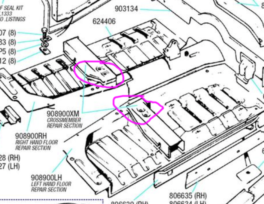
-
Same prop shaft for 3.27 and 3.89 differentials in a GT6 MKIII?
chrishawley replied to NDP's topic in Drivetrain & Rear Axle
3.27s are indeed rather scarce. Poss worth a look at https://www.ebay.co.uk/itm/225080199537?_trkparms=amclksrc%3DITM%26aid%3D111001%26algo%3DREC.SEED%26ao%3D1%26asc%3D20160811114145%26meid%3D77b648b22740446690b67422c79c730f%26pid%3D100667%26rk%3D2%26rkt%3D8%26sd%3D195231247885%26itm%3D225080199537%26pmt%3D0%26noa%3D1%26pg%3D2334524%26brand%3DTriumph&_trksid=p2334524.c100667.m2042 -
I was going to contribute as below but not sure was very helpful so have greyed it out. But going back to the top, for clarification: What's the issue or problem seeking a solution? Perhaps parts are required? Or an originality/athenticity question? Any further guidance in this respect would be good. ---- Just trawling through the SU book. It appears that were two variations of the HS2 for Spit3; to wit AUD257 and AUD275. The only difference I can find between AUD257 and AUD275 is BO needle as opposed to DD needle. If Spit4 HS2s are in the equation then there were two variations AUD 441 and AUD 580 which appear to differ from each other only in the throttle disc. ----.
-
K&Ns? It might be fair to say that opinions vary about the merits (and cost) of these. May I mention a cheap wheeze for rescuing pitted parts such as these? Derust, then rustproofing primer. Then srapy pitted area generously with stonechip. When rock solid dry can be sanded flat. Nothing clever about this really - just using stonechip as though it were a super tough high build primer.

-
13/60 randomly turning off or kicking back, high temps
chrishawley replied to Quack's topic in Engine
Just to correct my erroneous comment. The system is evidently full electronic and not points-assist. Apologies for duff comment. I had a comparable situation last year: partial failure of a (currrent) Accuspark unit giving unpredictable sudden deaths, but with revival when cool. Definitive diagnosis made by substitution with mechainical points. -
Reviews: Which magazine examined this matter a couple of years and the critique was devastating. Across a number of review platforms they found about a third of all reviews were faked, fraudelent, paid for, or written by machines. Now I know I really should get out more (!) but consider the Wickes Website for a bit of direct evidence. If 'drill' is entered as a search term then of the 479 items that are returned ALL are rated as 5 stars. Now repeat with the search term <brush>: of 160 products 5 star reviews are awarded to..............160 items. Rant over.
-
13/60 randomly turning off or kicking back, high temps
chrishawley replied to Quack's topic in Engine
Quack, I've been pondering your situ. and had a look back at the previous thread on running problems. Taking the broad view, there's such a diversity of symptoms that the it possible to make a case for all sort or prolems in all sorts of areas. For example: 'Sudden death and revival' implies electrical failure. Could be the High Tension side, but equally well LT ('supply') side could be a culprit as well. Lumpy misfire under load could be carb problems, or fuel supply problems or marked overheathing. So many possibilities it's hard to propose a concise line of investigation. But here's some suggestions, bearing in mind I'm taking some fairly wide guesses: After looking at the distributor, points condensor (etc) a possibility, for diagnostic purposes, is to hot-wire the coil i.e. simply take 12v straight down from the battery to + on the coil (removing the existing supply). If sudden death still occurs then at least that excludes supply side problems. If it abolishes otheriwse continuing SD then it points strongly to intermittment faults of the supply side wiring. Disconnect when test drive done!! Also of possible diagnostic assistance is to insert a transparent in line, paper, fuel filter between the carb and fuel pipe. Won't cure anything but enables the fuel supply to be directly inspected. And if any debris accumulates at all that indicates for further investigation of fuel pump, fuel lines and tank. Then there's the Accuspark unit. I vaguely think that the EI is not a true electronic system but, like the old Sparkrites, a 'points assist' system. I'd remove it simply to eliminate it from considerations. This engine should run on conventional points just fine. On my Spitfire I can switch between full electronic ignition and points-only on the fly and you'd be hard pressed to tell any difference. Last suggestion, for now, is that it might be time to revist the carb. I remember the picture of your diaphragm and to my eyes it's shot and needs replacement. But beyond that, removal from the car and full interogation on the bench is called for. Admittedly Strombergs are not quite as simple to work on as SUs - but really not that bad. If this carb has not be apart in living memory then it wouldn't surprise me to find (one or more of) advanced spindle wear, worn needle/jet, float chamber full of debris, needle value poorly operating. Not sure about the damper spring on 13/60s pehaps someone lese could shed light on that. All the above are guesses but I hope there's something in there of use. -
To clarify: Is that referring to the 3 studs exhaust manifold to downpipe, rather that cylinder head to exhuast manifold studs? On a Spitfire 1500? An embeliishment to the welded nut technique: If such a nut is lightly welded then the weld may yield before the thread does. Using MIG, weld as deeply and melty-inny as possible with max possible current and min possible wire. Then allow to fully, gradually, cool in air before spannering. The Achilles heel of the S1500 downpipe is the bracket that stabilises the downpipe to the right lowest stud on the gearbox. In particular the absence thereof. If missing then creating a suitable arrangement vastly improves the longevity of the manifold to downpipe joint.
-
GIRLING Type 14 Calipers. Pistons: Stainless v. Chrome? Seized.
chrishawley replied to chrishawley's topic in Braking System
That seems to be about a 50:50 split. Decisions, decisions! Just notices that RImmers so s/s pistons for the 14 caliper for, wait for it, £21 each. Wot! So my option to get 4 off for £45 looks like a snip by comparison. So on the grounds that I only have pay a few bob extra for warm glow, s/s/ it is. But the real warmy glowiness is in having Girling calipers with all the right numbers cast in etc. Oooohhhh. Seriously though. Seized calipers used to bother me a lot because of the tediousness of shifting a well stuck piston. My preferred method now, for any piston that won't give in easily to a puff of compressed air, is to weld steel bar to the piston and hoik it out. Sure it renders the piston unservicable, but a stuck piston is usually unservicable anyway. -
Quick reality check question here. Any opinions appreciated. Spitfire with genuine Girling calipers now unseized but need new pistons. Standard plated £25/axle set v. £50 for stainless. Is S/S worth the extra expenditure? Don't need to penny pinch this job but don't need to spend extra if it's for nothing. Suggestions? ---------------
-
" parallell bars and the steering lock
chrishawley replied to Ian Maxwell-Muller's topic in Chassis, Suspension & Steering
Popped out to garage to see if inspection of my GT6 would shed any light. But all assembled I can't see much, so no great insights. I'm deeply bamboozled as to how the the hole in the shroud for the coumn lock could not be in the right place. I'm curious to know of an answer. I have no idea, but is the collar for the locking pin machined on the upper mast or is it a fitment with a tight interference fit (and thus potentally moveable)? The only other thing which is occurs to me is that the upper 'bulb' of the shroud (where the light and indicator stalks attach) is a separate piece which becomes readily detached when you don't want. Hard to imagine, but might it have been previous detached and not fitted back deep enough? But I'm fishing for ideas rather than having any actual facts to go on. Do you have the the rubber surround for the ignition switch to hand? This can be a real rotter to fit so if you do have to drill a new hole it's possibly worth taking that into account when deciding on position. -
Just wondering if you've made any progress? Only just dawned on that this is not a half-shaft issue as such, but rather a generic seized fastener issue, just in a particularly-awkward-to-deal-with position. So in that respect it's all the 'usuals' for dealing with seized fasteners. Not a good position, though, for the use of heat. But including trying to tighten the nut(s) further since even a µgnats of movement can be enough to break the bond between nut and bolt. I've not been previously introduced to spanner extenders. But in similar vein; not infrequently I'll sacrifice a spanner by wedling (or even welding) it to some steel bar or cut the head off one end so a steel tube or box section can be slid over in order to extend. Given that set of budget spanners can still be had for less than a tenner sacrificing a tool can be the most efficient thing where time v. money is concerned.
-
Indicator switch wires rotted off.
chrishawley replied to Ian Maxwell-Muller's topic in Electrical System
For sure! The repros in the faux Luca box are not nice. I had one for a while but replaced with an original (bitza) one as soon as I could.


